Metal part cleaning device

A technology for cleaning devices and metal parts, applied in the field of cleaning, can solve problems such as reducing the useful life of equipment, increasing production costs, and damage to agitators, and achieves the effects of improving cleanliness, expanding the range of activities, and changing the contact area.

Inactive Publication Date: 2021-03-16
蔡晴雯
View PDF0 Cites 1 Cited by
  • Summary
  • Abstract
  • Description
  • Claims
  • Application Information

AI Technical Summary

Problems solved by technology

At this time, the agitator needs to be inserted into the cleaning solution, and the fan blades of the agitator are mostly made of steel. If pickling is used, the cleaning solution will cause damage to the agitator, reduce the practical life of the equipment, and increase production costs.

Method used


Image

  • Metal part cleaning device
  • Metal part cleaning device
  • Metal part cleaning device

Examples


Embodiment Construction

[0026] Embodiments of the present patent are described in detail below, examples of which are shown in the drawings, wherein the same or similar reference numerals designate the same or similar elements or elements having the same or similar functions throughout. The embodiments described below by referring to the figures are exemplary and are only used for explaining the patent, and should not be construed as limiting the patent.

[0027] In the description of this patent, it is to be understood that the terms "center", "upper", "lower", "front", "rear", "left", "right", "vertical", "horizontal", The orientation or positional relationship indicated by "top", "bottom", "inner", "outer", etc. is based on the orientation or positional relationship shown in the drawings, and is only for the convenience of describing this patent and simplifying the description, rather than indicating or implying References to devices or elements must have a particular orientation, be constructed, ...


PUM


Abstract

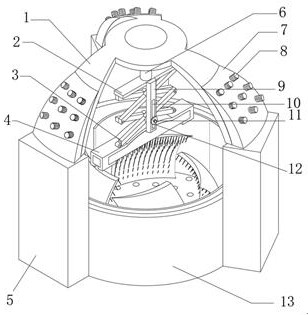
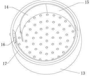
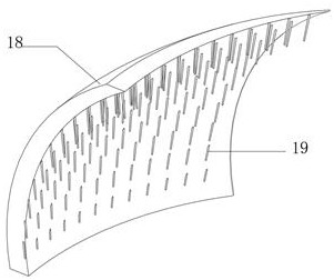
The invention discloses a metal part cleaning device. The metal cleaning device comprises a cleaning pool, multiple bottom frames distributed at equal angles are arranged on the outer wall of the cleaning pool, a supporting frame is arranged on the outer walls of the tops of the bottom frames, a motor is fixed to the bottom of the inner wall of the supporting frame, a transverse plate is fixed toan output shaft of the motor, a telescopic frame is movably connected to the outer wall of the bottom of the transverse plate, a fixed frame is movably connected to the bottom end of the telescopic frame, and a magnet is connected in the fixed frame in a clamped manner. A guide plate is fixedly connected to the outer wall of one side of the transverse plate, a strip-shaped groove is formed in theouter wall of the guide plate, a fixed rod is arranged on the inner wall of the strip-shaped groove, a pressing plate is in threaded connection with the outer wall of the fixed rod, and one end of thefixed rod is arranged on the outer wall of the telescopic frame. The arranged motor rotates to drive the magnet to rotate, the magnet drives a metal part to move, and therefore the effective contactarea of the metal part and cleaning liquid can be changed when no stirrer is in contact with the cleaning liquid.

Description

technical field [0001] The invention relates to the technical field of cleaning, in particular to a cleaning device for metal parts. Background technique [0002] Metal parts refer to parts made of metal materials, such as screws, nuts, springs and other objects. In the actual production and processing process, sometimes in order to facilitate the operation of a certain process, some greases are sometimes applied to the outer walls of these metal parts. Sometimes it is necessary to clean the workpiece after the process is finished, and separate the cleaned debris from the workpiece through the filter plate, which is conducive to maintaining the cleanliness of the cleaning solution. [0003] In the prior art, when cleaning metal parts, the metal parts to be cleaned are often placed in the cleaning pool, and the cleaning liquid is driven by the agitator to flow, so as to increase the effective contact area between the metal parts and the cleaning liquid. At this time, the ag...

Claims


Application Information

Patent Timeline
Patent Type & Authority Applications(China)
IPC IPC(8): B08B1/00B08B3/08B08B3/10B08B3/02B08B13/00
CPCB08B1/002B08B3/022B08B3/08B08B3/10B08B13/00
Inventor 蔡晴雯
Owner 蔡晴雯
Why Eureka
Try Eureka