Industrial iron bowl punching equipment

An industrial, punching technology, applied in the field of industrial iron bowl punching equipment, can solve problems such as complex structure

Pending Publication Date: 2021-03-16
谢艳珍
View PDF9 Cites 3 Cited by
  • Summary
  • Abstract
  • Description
  • Claims
  • Application Information

AI Technical Summary

Problems solved by technology

[0005] In order to overcome the complex structure of the prior art, many steps of manual operation are required, and after the punching is completed, the iron bowl needs to be manually removed. Light labor and no need for manual removal of iron bowls Industrial iron bowl punching equipment

Method used


Image

  • Industrial iron bowl punching equipment
  • Industrial iron bowl punching equipment
  • Industrial iron bowl punching equipment

Examples


Embodiment 1

[0029] An industrial iron bowl punching equipment, such as figure 1 and figure 2 As shown, it includes a base 1, a servo motor 2, a workbench 3, a punching mechanism 4 and a feeding mechanism 5. The front side of the top of the base 1 is provided with a servo motor 2, and the front side of the top of the base 1 is provided with a workbench 3. The servo motor 2 The output shaft rotates through the workbench 3, the base 1 is provided with a punching mechanism 4, and the punching mechanism 4 is provided with a retrieving mechanism 5.

[0030] When people need to use this equipment, people first place the iron circular plate on the punching mechanism 4, then start the servo motor 2, and the servo motor 2 drives the punching mechanism 4 to operate, and the punching mechanism 4 drives the material retrieving The mechanism 5 operates, and the stamping mechanism 4 operates to stamp the iron disc. After the stamping is completed, the retrieving mechanism 5 sucks the formed iron bowl,...

Embodiment 2

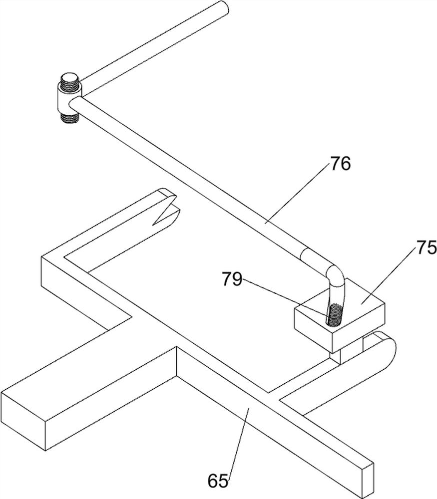
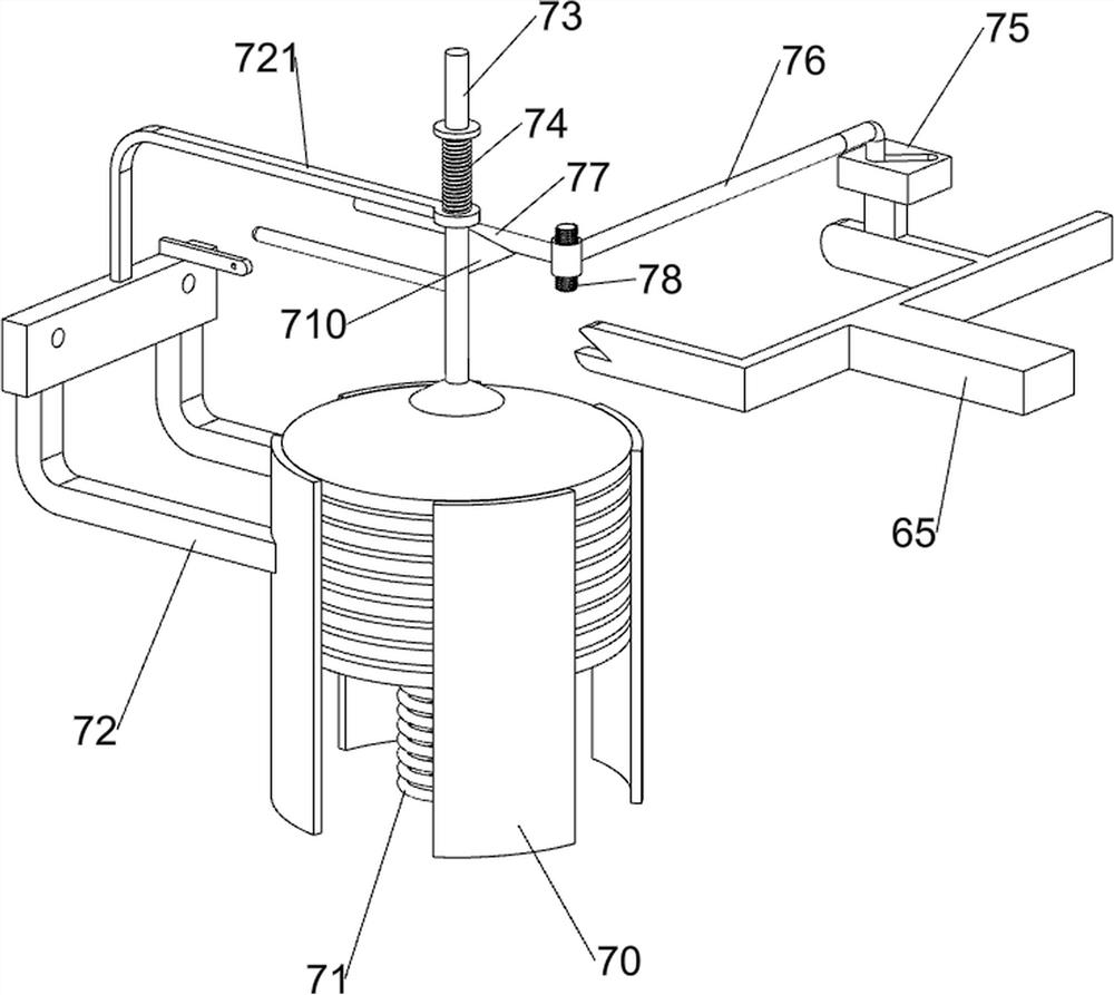
[0036] On the basis of Example 1, such as figure 1 , image 3 , Figure 4 , Figure 5 , Figure 6 , Figure 7 and Figure 8 Shown, also comprise intermittent feeding mechanism 6, intermittent feeding mechanism 6 includes second slide block 60, first slide rail 61, turning bar 62, second slide rail 63 and feeding frame 65, workbench 3 left and right sides The side sliding type is provided with a second slide block 60, the second slide block 60 is provided with a first slide rail 61, the output shaft of the servo motor 2 is provided with a rotating rod 62, and a second slide rail 61 is provided between the first slide rails 61. Slide rail 63, a chute 64 is provided on the workbench 3, a material delivery frame 65 is slidingly provided between the first slide rail 61 and the second slide rail 63, and the lower part of the material delivery frame 65 is in the rotating rod 62 and the chute 64 slide.

[0037] After the servo motor 2 is started, the output shaft of the servo m...


PUM


Abstract

The invention relates to punching equipment, in particular to industrial iron bowl punching equipment. By means of the industrial iron bowl punching equipment, the labor intensity of workers can be relieved, and iron bowls do not need to be manually taken down. The industrial iron bowl punching equipment comprises a base, a workbench, a punching mechanism and a taking mechanism, wherein a servo motor is arranged at the top of the base, the workbench is arranged at the top of the base, the punching mechanism is arranged on the base, and the taking mechanism is arranged on the punching mechanism. According to the industrial iron bowl punching equipment, the servo motor is started to enable the punching mechanism to operate, and then punching of the iron bowls is performed through the cooperation of the punching mechanism and the taking mechanism. The taking mechanism can attract the iron bowls obtained after punching, then the iron bowls are separated from the punching mechanism, and then the workers can conveniently take down the iron bowls.

Description

technical field [0001] The invention relates to a punching equipment, in particular to an industrial iron bowl punching equipment. Background technique [0002] As people's daily necessary eating utensils, bowls are mostly round, and their general purpose is to hold food. Most Chinese people like to use bowls as eating tools. [0003] Bowls are made of ceramics, wood, jade, glass, colored glaze, metal, etc.; exquisitely crafted antique bowls are often favorites of collectors. At present, most of the bowls used by people are made of iron and stainless steel. Iron bowls are on sale It usually needs to talk about multiple processes before, and stamping is one of the important processing steps. When stamping iron bowls, the worker first needs to place the iron disc on the workbench, and then manually operate the stamping equipment Stamping the iron disc, but most of the existing stamping equipment has a complex structure, requiring many steps of manual operation, and after the...

Claims


Application Information

Patent Timeline
Patent Type & Authority Applications(China)
IPC IPC(8): B21D22/02B21D43/24B21D43/02B21D43/18B21D43/13B21D45/08B21D51/18
CPCB21D22/02B21D43/24B21D43/026B21D43/18B21D43/13B21D45/08B21D51/18
Inventor 不公告发明人
Owner 谢艳珍
Why Eureka
Try Eureka