

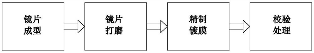
High-definition camera lens manufacturing process
A high-definition camera and manufacturing process technology, applied in manufacturing tools, glass manufacturing equipment, metal processing equipment, etc., can solve problems such as being difficult to disperse, affecting workers' health, polluting the environment, and avoiding relative sliding up and down.
- Summary
- Abstract
- Description
- Claims
- Application Information
AI Technical Summary
Problems solved by technology
Method used
Image

Examples
Embodiment Construction
[0038] The embodiments of the present invention will be described in detail below with reference to the accompanying drawings, but the present invention can be implemented in many different ways defined and covered by the claims.
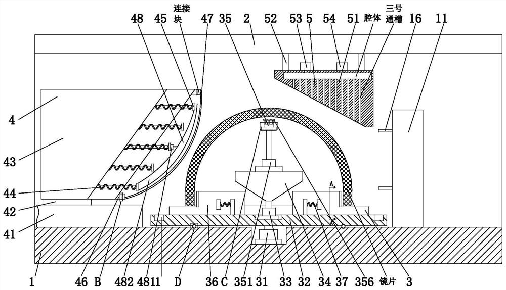
[0039] Such as Figure 1 to Figure 9 As shown, a high-definition camera lens manufacturing process, the high-definition camera lens manufacturing process uses a camera lens manufacturing device, the camera lens manufacturing device includes a bottom frame 1, a vertical frame 2, an inner clamping mechanism 3 , grinding mechanism 4 and spraying mechanism 5, the vertical frame 2 is installed on the front side of the upper end of the bottom frame 1, the inner clamping mechanism 3 is installed on the upper end surface of the bottom frame 1, and the upper end surface of the bottom frame 1 is located in the inner Grinding mechanism 4 is installed on the left side of clamping mechanism 3 , and spraying mechanism 5 is installed on the right side of inner cla...
PUM
 Abstract
Description
Claims
Application Information