Industrial grinding machine

A grinding machine and industrial technology, applied in the field of machinery, can solve the problem of inconvenient cleaning of grinding wheels, and achieve the effect of easy cleaning

Active Publication Date: 2021-03-16
湖南嘉顺华新材料有限公司
View PDF8 Cites 0 Cited by
  • Summary
  • Abstract
  • Description
  • Claims
  • Application Information

AI Technical Summary

Problems solved by technology

[0002] Now there is a patent number: CN201520303937.6 industrial grinding machine, which discloses an industrial grinding machine, including a base, a support rod is arranged at both ends of the base, and the upper end surface of each support rod is perpendicular to the support The rod is provided with a top plate, and the inner surface of the top plate is respectively provided with a shaft hole, and a shaft rod is arranged in the shaft hole, and a square-shaped casing is installed between the two shaft rods, and the two sides of the casing are arranged There is a shaft hole, an isolation net is arranged on the upper end of the casing, a cover plate is arranged on the upper end of the isolation net, a materi

Method used


Image

  • Industrial grinding machine
  • Industrial grinding machine
  • Industrial grinding machine

Examples


specific Embodiment approach 1

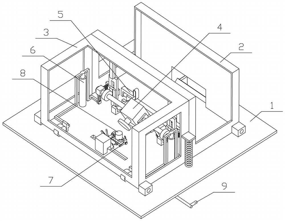
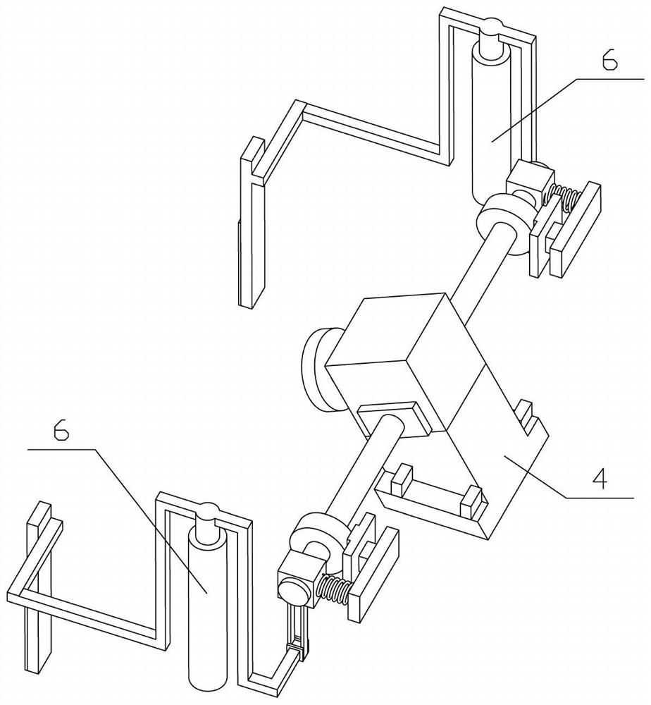
[0035] Combine below Figure 1-14 Describe this embodiment, the present invention relates to the field of mechanical technology, more specifically an industrial grinding machine, including a carrying device 1, a fixed box 2, a rotating box 3, a grinding device 4, a locking device 5, a lifting device 6, and a clamping device 7. The workpiece 8 and the adjustment device 9, the present invention has the function of facilitating the cleaning of the grinding runner.

[0036] The right end of the upper part of the carrying device 1 is fixedly connected with a fixed box 2, and the left end of the upper part of the carrying device 1 is hingedly connected with a rotary box 3. A grinding device 4 is installed on the carrying device 1, and the grinding device 4 can be connected to the carrying device by a locking device 5. The device 1 is fixed, and the front and rear ends of the upper part of the carrying device 1 are symmetrically fixedly connected with two lifting devices 6. A lifting ...

specific Embodiment approach 2

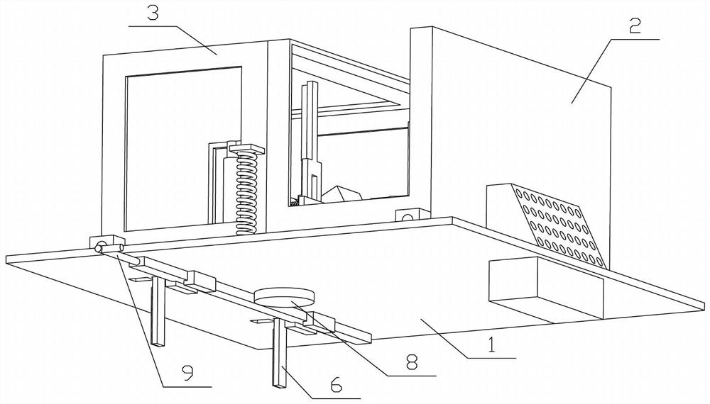
[0038] Combine below Figure 1-14 Describe this embodiment, this embodiment will further explain the first embodiment, the carrying device 1 includes a carrying plate 1-1, a rotating shaft block 1-2, a blocking plate 1-3, a dust box 1-4, and a vertical column 1 -5. Rack I 1-6 and L-shaped plate 1-7, the four corners above the bearing plate 1-1 are fixedly connected with rotating shaft blocks 1-2, and the plurality of rotating shaft blocks 1-2 are divided into left and right groups, The right end above the load plate 1-1 is fixedly connected with a blocking plate 1-3, the right end below the load plate 1-1 is fixedly connected with a dust box 1-4, and the front and rear ends of the upper middle of the load plate 1-1 are fixedly connected with a Vertical columns 1-5, the left sides of the two vertical columns 1-5 are fixedly connected with rack I1-6, and the front and rear ends of the left side under the bearing plate 1-1 are symmetrically fixedly connected with two L-shaped pla...

specific Embodiment approach 3

[0040] Combine below Figure 1-14 Describe this embodiment, this embodiment will further explain embodiment two, described fixed box 2 comprises fixed box box body 2-1, transition box 2-2 and air vent 2-3, fixed box box body 2-1 Fixedly connected on the bearing plate 1-1, the right end of the fixed box body 2-1 is fixedly connected with the transition box 2-2, the transition box 2-2 is located above the dust collection box 1-4, and the bottom of the transition box 2-2 Open, the transition box 2-2 is provided with a plurality of ventilation holes 2-3, and the front and rear ends of the fixed box body 2-1 are respectively inserted into the two rotating shaft blocks 1-2 at the right end; the ventilation holes 2-3 have Ventilation function, when blowing to the transition box 2-2, the airflow blows the ground powder to the ventilation hole 2-3, the powder is blocked by the slope at the right end of the transition box 2-2, and finally falls into the dust box 1 In -4, the collection...


PUM


Abstract

The invention relates to the technical field of machinery, in particular to an industrial grinding machine. The industrial grinding machine comprises a bearing device, a fixed box, a rotating box, a grinding device, a locking device, lifting devices, a clamping device, a workpiece and an adjusting device. The right end of the upper portion of the bearing device is fixedly connected with the fixedbox, the left end of the upper portion of the bearing device is connected with the rotating box in a hinged manner, and the grinding device is installed on the bearing device. The grinding device andthe bearing device can be fixed through the locking device, the front end and the rear end of the upper portion of the bearing device are symmetrically and fixedly connected with the two lifting devices, the two lifting devices are both in sliding connection with the bearing device and are both in engaged transmission connection with the rotating box, and the two lifting devices are in sliding connection with the front end and the rear end of the grinding device correspondingly. The clamping device is rotatably connected to the middle of the bearing device, the workpiece can be clamped throughthe clamping device, and the adjusting device is in sliding connection to the bearing device and is in engaged transmission connection with the clamping device. The industrial grinding machine has the function of conveniently cleaning a grinding tool bit.

Description

technical field [0001] The invention relates to the technical field of machinery, and more specifically relates to an industrial grinder. Background technique [0002] Now there is a patent number: CN201520303937.6 industrial grinding machine, which discloses an industrial grinding machine, including a base, a support rod is arranged at both ends of the base, and the upper end surface of each support rod is perpendicular to the support The rod is provided with a top plate, and the inner surface of the top plate is respectively provided with a shaft hole, and a shaft rod is arranged in the shaft hole, and a square-shaped casing is installed between the two shaft rods, and the two sides of the casing are arranged There is a shaft hole, an isolation net is arranged on the upper end of the casing, a cover plate is arranged on the upper end of the isolation net, a material cavity is formed between the cover plate and the isolation net, and a pressure plate is arranged on both sid...

Claims


Application Information

Patent Timeline
IPC IPC(8): B24B37/00B24B47/12B24B37/27B24B37/34B24B55/06B24B47/22
CPCB24B37/00B24B37/27B24B37/34B24B47/12B24B47/22B24B55/06
Inventor 张明辉
Owner 湖南嘉顺华新材料有限公司
Why Eureka
Try Eureka