Supercharge Your Innovation With Domain-Expert AI Agents!

Flow guide system for wind power blade girder pouring

A technology of wind power blades and girders, which is applied in the field of diversion systems for the perfusion of wind power blade girders. It can solve the problems of very high flatness requirements for the laying of diversion media, problems such as infusion quality problems that cannot be completely avoided, and air pumping bag seal failures. Promote the value, shorten the perfusion time, and the effect of reasonable structural design

Pending Publication Date: 2021-03-16
江苏双瑞风电叶片有限公司
View PDF0 Cites 1 Cited by
  • Summary
  • Abstract
  • Description
  • Claims
  • Application Information

AI Technical Summary

Problems solved by technology

At present, the girders of wind power blades are mainly formed by vacuum infusion, and the diversion systems used to prepare the girders have certain quality problems: (1) The diversion system is poured from the lower surface of the product to the upper surface and added with a suction bag on the upper surface Among them, if the air suction bag is not tightly sealed, it is easy to fail, resulting in perfusion defects on the upper surface. At the same time, the flatness of the laying of the diversion medium on the lower surface is very high, which will easily lead to beam folds, serious or even scrapped; (2) from the upper surface The diversion system poured into the lower surface is prone to infusion defects on the lower surface; (3) The diversion system in which the resin is poured from the upper and lower surfaces to the middle of the product is prone to defects on the side without the diversion net on the upper surface, and also leads to defects on the lower surface. The flatness requirements of fluid media laying are very high
[0003] Although there are many types of diversion systems used to prepare girders, it is still impossible to completely avoid the occurrence of perfusion quality problems on the basis of constant changes in factors such as temperature, humidity, and raw materials.

Method used


Image

  • Flow guide system for wind power blade girder pouring

Examples


Embodiment Construction

[0024] The technical solution of the present invention will be clearly and completely described below in conjunction with specific embodiments. Apparently, the described embodiments are only a part of the embodiments of the present invention, not all of them. Based on the embodiments of the present invention, all other embodiments obtained by persons of ordinary skill in the art without making creative efforts belong to the protection scope of the present invention.

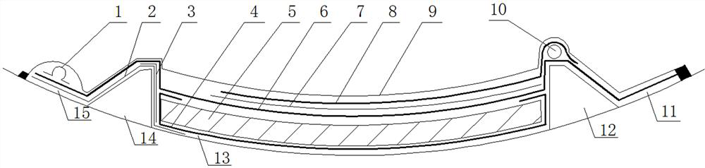
[0025] A guide system for pouring wind turbine blade girders, please refer to figure 1 , the diversion system includes a girder mould, the girder mold includes a main body area 13, the two sides of the main body area 13 are provided with a left rib 14 and a right rib 12 with a quadrangular cross-section, and the left side of the left rib 14 is provided with a left auxiliary Area 15, the right auxiliary area 11 is set on the right side of the right rib 12; the main area 13 is laid with the first release cloth 4, t...


PUM

PropertyMeasurementUnit
Widthaaaaaaaaaa

Abstract

The invention discloses a flow guide system for wind power blade girder pouring. The flow guide system comprises a girder formwork, the girder formwork comprises a body area, a left flange and a rightflange are arranged on the two sides of the body area, a left auxiliary area is arranged on the left side of the left flange, and a right auxiliary area is arranged on the right side of the right flange; first demolding cloth, a girder laying layer, second demolding cloth, a first perforated isolation film, a flow guide net and a vacuum bag film are sequentially laid in the body area from bottomto top, and the left ends and the right ends of the second demolding cloth and the vacuum bag film are fixed to the left auxiliary area and the right auxiliary area correspondingly. the second demoulding cloth and the vacuum bag film are laid on the left flange, the left flange is further provided with a VAP air exhaust bag and a second perforated isolation film, and the VAP air exhaust bag is aslong as a girder to be manufactured; and a spiral pipe located between the second demolding cloth and the flow guide net is arranged at the top of the right flange, an ohm pipe is arranged at the position, above the second demolding cloth, of the left auxiliary area, and the ohm pipe with the length equal to that of the girder to be manufactured is connected with the VAP air exhaust bag. The flowguide system can prevent pouring defects from being generated, and the stability of girder pouring quality is guaranteed.

Description

technical field [0001] The invention relates to the technical field of forming a wind power blade girder, in particular to a flow guiding system for pouring a wind power blade girder. Background technique [0002] With the increasing demand for high-power and large-size blades in the wind power industry, the design thickness of the girder is also increasing. As one of the important load-bearing components in wind power blades, the girder’s pouring quality plays a decisive role in the quality of the blade. At present, the girders of wind power blades are mainly formed by vacuum infusion, and the diversion systems used to prepare the girders have certain quality problems: (1) The diversion system is poured from the lower surface of the product to the upper surface and added with a suction bag on the upper surface Among them, if the air suction bag is not tightly sealed, it is easy to fail, resulting in perfusion defects on the upper surface. At the same time, the flatness of t...

Claims


Application Information

Patent Timeline
IPC IPC(8): B29C70/36B29C70/54B29L31/08
CPCB29C70/36B29C70/54B29L2031/085
Inventor 李轲赵金国任令响牛世军
Owner 江苏双瑞风电叶片有限公司
Features
  • R&D
  • Intellectual Property
  • Life Sciences
  • Materials
  • Tech Scout
  • Unparalleled Data Quality
  • Higher Quality Content
  • 60% Fewer Hallucinations
Learn More