
Imprinting device for outer wall of iron bottle for production of fruit juice

A technology for bottle caps and fruit juices, applied in the field of embossing devices, which can solve the problems of high equipment cost, inability to save time and labor, and complicated operation process, and achieve the effect of increasing accuracy

Inactive Publication Date: 2021-03-16
钟珊
View PDF10 Cites 6 Cited by
  • Summary
  • Abstract
  • Description
  • Claims
  • Application Information

AI Technical Summary

Problems solved by technology

[0004] In order to overcome the complex structure of the existing juice bottle cap imprinting device, there are many places where manual operation is required, and the operation process is relatively complicated, it cannot achieve the effect of saving time and effort, the equipment cost is high, and the existing operating technology is limited. The disadvantage of low precision, the technical problem to be solved: to provide a time-saving and labor-saving, simple structure, simple operation and high precision stamping device for the outer wall of iron bottle caps for fruit juice production

Method used


Image

  • Imprinting device for outer wall of iron bottle for production of fruit juice
  • Imprinting device for outer wall of iron bottle for production of fruit juice
  • Imprinting device for outer wall of iron bottle for production of fruit juice

Examples


Embodiment 1

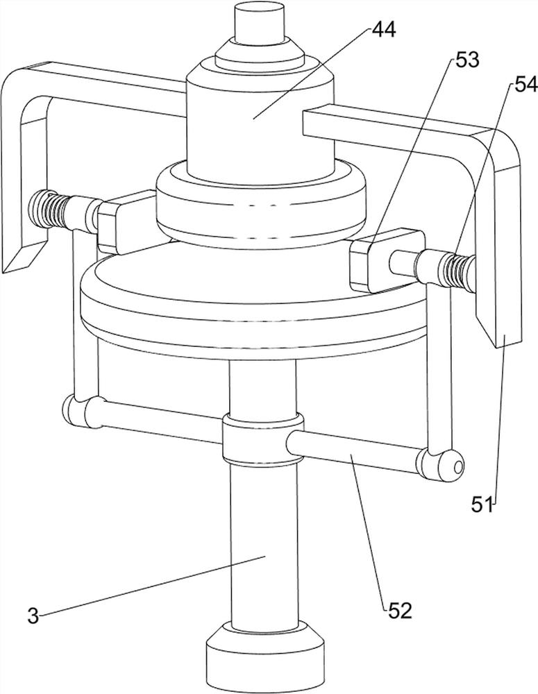
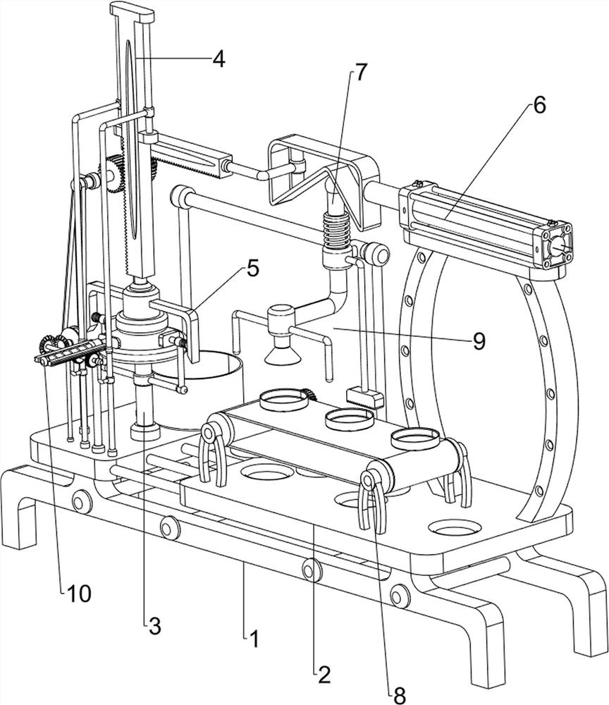
[0070] An outer wall pressure printing device for producing iron bottle of juice, such as figure 1 As shown, there is a base 1, the mounting plate 2, the support station 3, the lower pressure mechanism 4, and the clamping mechanism 5, and the top of the base 1 is provided with a mounting plate 2, and the mounting plate 2 is provided with a support station 3, and the mounting plate 2 is provided. The lower left side is provided with a lower pressure mechanism 4, and the lower pressure mechanism 4 is fitted with the support table 3, and the support table 3 and the lower pressure mechanism 4 are provided with a clamping mechanism 5.

[0071] It can be printed by the present invention, first, the operator is placed on the support table 3, followed by pressing the lower pressing mechanism 4, and the lower pressure mechanism 4 will press the cap to press the bottle cover, down pressure mechanism 4 Down movement, the clamping mechanism 5 is clamped from both sides, and after the lower p...

Embodiment 2

[0073] On the basis of Example 1, such asfigure 2 with image 3 As shown, the lower pressure mechanism 4 includes a first slip sleeve 41, a first slider 42, a first rack 43, and a printing block 44, and two first sliders 41 are provided on the front of the top of the mounting plate 2. The first slider 41 is slidably equipped with a first slider 43, and a first rack 43 is provided between the two first sliders 42, and a printing block 44 is provided at the bottom of the first rack 43.

[0074] The lower pressure mechanism 4 is moved downward, and the top of the bottle cap is imprinted. First, the operator places the bottle cover on the support table 3, and then press the first rack 43 downward, the first rack 43 moves downward. The first slider 42 slides downward on the first slider 41, so that the printing block 44 is driven down the bottle cover, the support table 3 is used to support the cap and the printing block 44, when the bottle cover is completed Thereafter, the first rac...

Embodiment 3

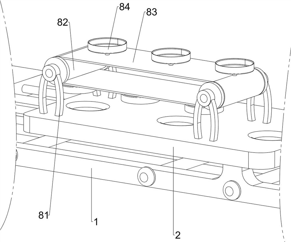
[0078] On the basis of Example 2, such as Figure 4 , Figure 5 , Figure 6 , Figure 7 with Figure 8 As shown, it is also included, and the push mechanism 6 includes a push mechanism 6 including a first support post 61, a cylinder 62, a second wedge block 63, a second rack 64, a second support post 65, a first spindle 66, and a first gear. 67. The first support post 61 is provided on the top right side of the mounting plate 2, and the upper portion of the first support post 61 is provided with a cylinder 62, and the second wedge block 63 is provided on the left side of the telescopic rod of the cylinder 62, and the second wedge block 63 is provided. There is a second rack 64, and the upper left side of the mounting plate 2 is provided with a second support post 65. The upper rotation of the second support post 65 is provided with a first spindle 66, and the first spindle 66 is provided with a first gear 67, first The gear 67 meshes with the first rack 43 and the second rack 64, r...


PUM


Abstract

The invention relates to an imprinting device, in particular to an imprinting device for an outer wall of an iron bottle for production of fruit juice. The imprinting device for the outer wall of theiron bottle for production of the fruit juice, which is time-saving and labor-saving, has a simple structure, is easy to operate and is higher in accuracy, is provided. The imprinting device for the outer wall of the iron bottle for production of the fruit juice comprises a base, a mounting plate, a supporting table, a press-down mechanism and clamping mechanisms, wherein the mounting plate is arranged on the base; the supporting table is arranged on the mounting plate; the press-down mechanism is arranged on the mounting plate and is matched with the supporting table; and the clamping mechanisms are arranged on the supporting table and the press-down mechanism. According to the imprinting device disclosed by the invention, through arrangement of a pushing mechanism, the pushing mechanismcan realize that the press-down mechanism is automatically driven to press a bottle cover downwards; and through arrangement of a material feeding mechanism, the material feeding mechanism can realizecontinuous supplementation of bottle covers, can control the accuracy of positions of the bottle covers, and can achieve the increase of accuracy for imprinting logos onto the bottle covers.

Description

Technical field [0001] The present invention relates to an imprint apparatus, and more particularly to a juice production iron bottle cover outer wall press printing device. Background technique [0002] Some trademark logo embossed needs bottle cap containing juice, used in some stamp trademark upper platen ready made bottle, it can be used to identify different brands of products, the conventional imprint apparatus juice cap The structure is more complicated, using more places where manual operation is required, and the operation process is more complicated, and the effect of saving time and effort can not be reached, the equipment cost is high, and the existing operating technique is less accurate. [0003] In conjunction with some of the above-mentioned disadvantages, it is urgent to develop an external wall press printing apparatus for saving time and effort, simple structure, simple operation, and high accuracy. Inventive content [0004] In order to overcome the existing ...

Claims


Application Information

Patent Timeline
Patent Type & Authority Applications(China)
IPC IPC(8): B41K3/04B41K3/48B41K3/52B41K3/62
CPCB41K3/04B41K3/48B41K3/52B41K3/62
Inventor 钟珊
Owner 钟珊
Learn More