
A combined flame stabilizer afterburner structure and control method

A flame stabilizer and afterburner technology, which is applied in the direction of combustion methods, combustion chambers, continuous combustion chambers, etc., can solve problems such as the narrow working boundary of the stabilizer, shorten the spontaneous combustion time, reduce the risk of surge, and improve the backflow area range effect

Active Publication Date: 2022-03-11
INST OF ENGINEERING THERMOPHYSICS - CHINESE ACAD OF SCI
View PDF0 Cites 0 Cited by
  • Summary
  • Abstract
  • Description
  • Claims
  • Application Information

AI Technical Summary

Problems solved by technology

In order to reduce the loss, the new flame stabilizer has added more flame stabilizing structures, but due to the narrow working boundary of the stabilizer, it has not been widely used

Method used


Image

  • A combined flame stabilizer afterburner structure and control method
  • A combined flame stabilizer afterburner structure and control method
  • A combined flame stabilizer afterburner structure and control method

Examples


Embodiment Construction

[0041] In order to make the objectives, technical solutions and advantages of the present invention clearer, the technical solutions in the embodiments of the present invention will be described in more detail below in conjunction with the drawings in the embodiments of the present invention. In the drawings, the same or similar reference numerals denote the same or similar elements or elements having the same or similar functions throughout. The described embodiments are some, but not all, embodiments of the invention. The embodiments described below by referring to the figures are exemplary and are intended to explain the present invention and should not be construed as limiting the present invention. Based on the embodiments of the present invention, all other embodiments obtained by persons of ordinary skill in the art without creative efforts fall within the protection scope of the present invention. The structure and technical solutions of the present invention will be ...


PUM


Abstract

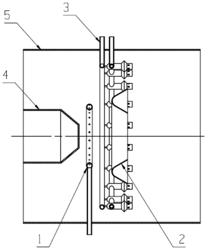
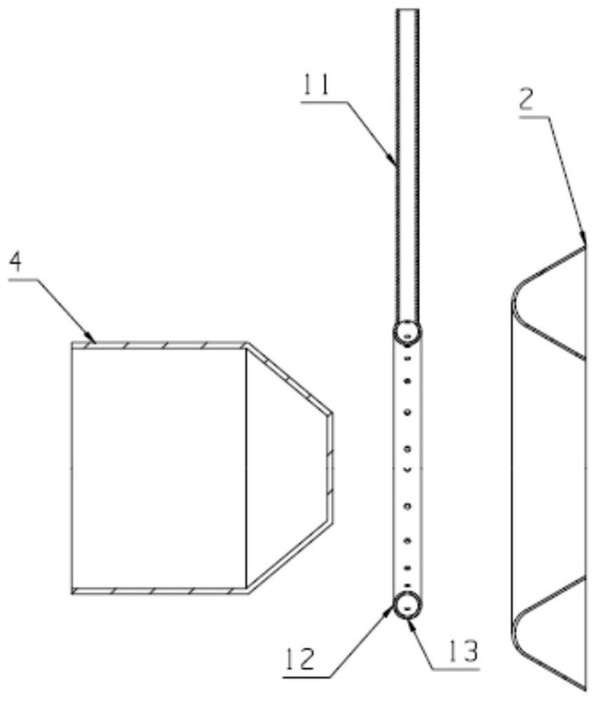
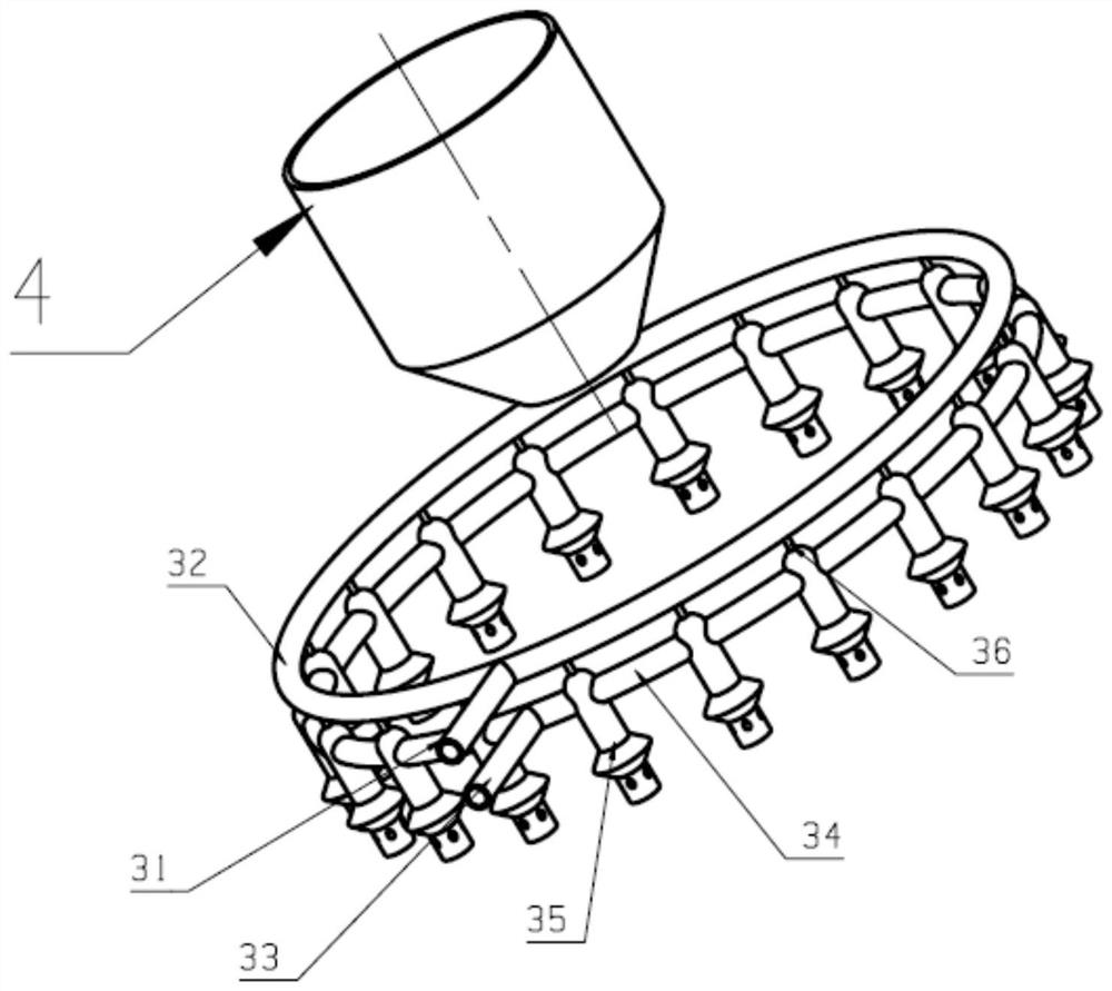
The invention relates to a structure and a control method of an afterburner combustion chamber of a combined flame stabilizer, which adopts the combined mode of aerodynamic flame stabilization and mechanical flame stabilization, and is suitable for the working requirements of aviation turbine engines and different afterburning states. The outer ring pneumatic flame stabilizer is mainly used for working under the state of high afterburner, and the inner ring mechanical flame stabilizer is mainly used for ignition and working under the state of small afterburner. The inner ring mechanical flame stabilizer has a fixed size, which can ensure the size of the recirculation zone behind the blunt body and play a role in stabilizing the ignition source. It is located inside the afterburner chamber and has a small circumferential dimension, which can reduce the clogging ratio of the afterburner chamber , to reduce afterburner flow losses. The radial geometric section size of the outer ring aerodynamic flame stabilizer is smaller than the radial geometric size of the inner ring mechanical flame stabilizer. When the afterburner is not turned on, there is only a geometric blockage ratio and flow loss, which can effectively reduce the non-afterburner of the aero turbine engine. Thrust loss in the state, improve the thrust-to-weight ratio.

Description

technical field [0001] The invention belongs to the technology of an aero turbine engine with an afterburner, and in particular relates to an afterburner structure and a control method for a combined flame stabilizer. Background technique [0002] At present, aeroengines with afterburners are organized combustion, and flame stabilizers are often used to construct the recirculation zone to ensure stable combustion of the flame. The traditional flame stabilizer uses a fixed-sized mechanical blunt body to construct the recirculation zone. In order to ensure the size of the recirculation zone, the flame stabilizer usually has a large geometric size, and the radial width is generally 30mm to 45mm, but this makes the afterburner Larger clogging ratio and greater pressure loss reduce the performance of the afterburner. Then a variety of flame stabilizer structures and integrated schemes were developed, such as suction flame stabilizers, pneumatic flame stabilizers, evaporative fla...

Claims


Application Information

Patent Timeline
Patent Type & Authority Patents(China)
IPC IPC(8): F23R3/20
CPCF23R3/20
Inventor 穆勇王于蓝阮昌龙刘存喜刘富强杨金虎王少林徐纲朱俊强
Owner INST OF ENGINEERING THERMOPHYSICS - CHINESE ACAD OF SCI
Learn More