
A solenoid magnetic field measurement system and its application method

A magnetic field measurement and solenoid technology, applied in the direction of the size/direction of the magnetic field, can solve the problems such as the inability to measure the declination angle between the magnetic axis and the mechanical axis, the cumbersome measurement process, and the complicated use of equipment, etc., to achieve high test efficiency, principle Simple, clear and easy to operate

Active Publication Date: 2021-11-09
INST OF MODERN PHYSICS CHINESE ACADEMY OF SCI
View PDF7 Cites 0 Cited by
  • Summary
  • Abstract
  • Description
  • Claims
  • Application Information

AI Technical Summary

Problems solved by technology

[0004] Measuring the deviation data between the solenoid magnetic axis and the mechanical axis is essential in the installation and use of electronic cooling solenoids. Traditional solenoid magnetic field measurement methods such as Hall plate point measurement can only obtain the data in the solenoid aperture. The magnetic field distribution of the solenoid cannot be measured to obtain the deflection angle between the magnetic axis and the mechanical axis; and the new test method such as the tension line measurement method can measure and calibrate the magnetic axis of the solenoid, but the equipment is complex, expensive and the measurement process is cumbersome.

Method used


Image

  • A solenoid magnetic field measurement system and its application method
  • A solenoid magnetic field measurement system and its application method
  • A solenoid magnetic field measurement system and its application method

Examples


Embodiment Construction

[0046] The present invention will be described in detail below in conjunction with the accompanying drawings. However, it should be understood that the accompanying drawings are provided only for better understanding of the present invention, and they should not be construed as limiting the present invention. In the description of the present invention, it should be understood that the terms "first", "second" and so on are only used for the purpose of description, and should not be understood as indicating or implying relative importance.

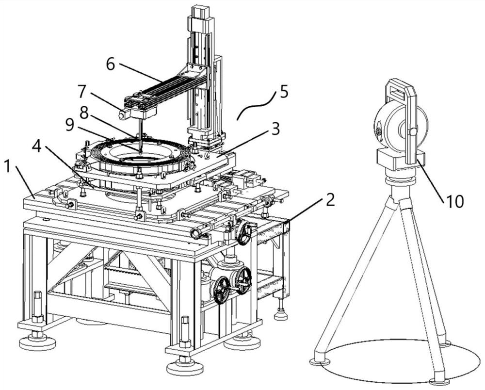
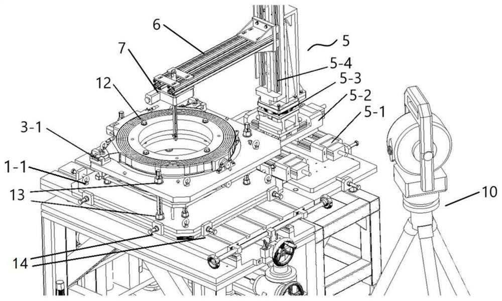
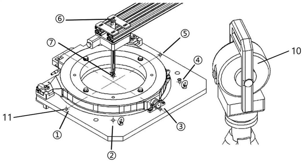
[0047] Such as figure 1 , figure 2 and image 3 As shown, the solenoid magnetic field measurement system provided by the present invention includes a first support platform 1, a second support platform 2, an adjustable reference platform 3, an adjustable coil support plate 4, a three-dimensional translation platform 5, a measurement arm 6, an electric rotating Table 7, measuring rod 8, measuring probe 9, laser tracker 10, target base 11...


PUM


Abstract

The invention relates to a solenoid magnetic field measurement system and its use method, which is characterized in that it includes an adjustable reference platform, an adjustable coil support plate, a three-dimensional translation platform, a measuring arm, an electric rotating platform, a measuring probe, a laser tracker and The controller; the adjustable coil supporting plate is arranged under the adjustable reference platform; the installation reference parts are arranged symmetrically on the top and bottom of the adjustable reference platform; the three-dimensional translation platform is set on one side of the adjustable reference platform, and the top of the three-dimensional translation platform slides One end of the measuring arm is connected, and the other end of the measuring arm is slidably connected to the electric rotary table, and the electric rotary table is fixedly connected to the measuring probe through the measuring rod, and the measuring probe is used to measure the axial magnetic field and the radial magnetic field; both the adjustable reference platform and the measuring rod are A target seat is provided, and the laser tracker is used to track the position of the target ball on the target seat; the controller is respectively connected with a three-dimensional translation platform, an electric rotating platform and a measuring probe. The present invention can be widely used in the field of accelerator magnetic field measurement.

Description

technical field [0001] The invention relates to a solenoid magnetic field measurement system and a using method thereof, belonging to the field of accelerator magnetic field measurement. Background technique [0002] Since the electron cooling method was proposed by the scientist Budeker in 1966, it has achieved remarkable development in the field of heavy ion accelerator engineering, and has been widely used in some large-scale accelerator experimental devices. The principle of electron cooling is to inject a certain required electron beam into the heavy ion beam. When the electron beam moves parallel to the heavy ion beam at the same speed, the Betatron oscillation of the ion beam will be reduced through the Coulomb interaction (that is, the particles in the circular accelerator The lateral motion in is a constrained oscillation about the design orbit). This is because the light electrons take away a large part of the ion energy through the Coulomb scattering with the ion...

Claims


Application Information

Patent Timeline
Patent Type & Authority Patents(China)
IPC IPC(8): G01R33/02
CPCG01R33/02
Inventor 杨颜冰陆海娇杨文杰沙小平冒立军马力祯赵丽霞吴巍陈文军柴志良
Owner INST OF MODERN PHYSICS CHINESE ACADEMY OF SCI
Learn More