
Calibration device and calibration method for setting values of multiple voltage monitors

A technology of a voltage monitor and a verification device, which is applied in the field of instrument detection, can solve the problems of long time consumption, voltage monitor setting value error, setting value error, etc., and achieves the effect of reducing communication pressure and improving accuracy

Active Publication Date: 2021-03-16
QINGYUAN POWER SUPPLY BUREAU OF GUANGDONG POWER GRID CO LTD
View PDF10 Cites 0 Cited by
  • Summary
  • Abstract
  • Description
  • Claims
  • Application Information

AI Technical Summary

Problems solved by technology

[0003] At present, there is equipment on the market that can simultaneously verify multiple voltage monitors, but the verification of the setting value of the voltage monitor by this device not only takes a long time, but also leads to low verification efficiency of the voltage monitor, and the upper computer The communication pressure is high, so there is a problem of delay in information transmission, which leads to a larger error in the setting value of the verified voltage monitor than the actual setting value of the voltage monitor

Method used


Image

  • Calibration device and calibration method for setting values of multiple voltage monitors
  • Calibration device and calibration method for setting values of multiple voltage monitors
  • Calibration device and calibration method for setting values of multiple voltage monitors

Examples


Embodiment Construction

[0028] In order to make the purpose, technical solutions and advantages of the embodiments of the present invention clearer, the technical solutions in the embodiments of the present invention will be clearly and completely described below in conjunction with the drawings in the embodiments of the present invention. Obviously, the described embodiments It is a part of embodiments of the present invention, but not all embodiments. Based on the embodiments of the present invention, all other embodiments obtained by persons of ordinary skill in the art without creative efforts fall within the protection scope of the present invention.

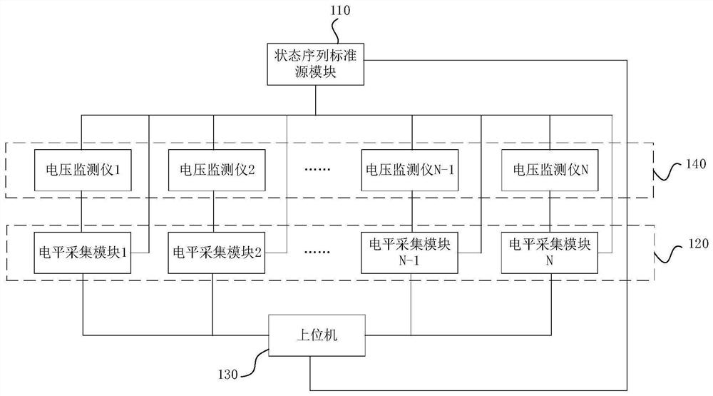
[0029] According to the research of the inventors, it is found that in the prior art, the detection time of multiple voltage monitors at the same time is relatively long, and most of the verification time is spent on the verification of the setting value of the voltage monitors. The verification of the setting value of the voltage monitor by the d...


PUM


Abstract

The invention discloses a calibration device and calibration method for setting values of multiple voltage monitors. The device comprises a state sequence standard source module, at least two level acquisition modules and an upper computer; the state sequence standard source module is connected with at least two voltage monitors and the at least two level acquisition modules, and is used for providing detection voltage signals for the voltage monitors and performing synchronous time synchronization with the level acquisition modules, and the voltage values of the detection voltage signals aregradually increased or decreased according to a preset step length; the level acquisition modules are connected with the voltage monitors in a one-to-one correspondence manner and are used for acquiring alarm signals sent by the voltage monitors and determining the time for sending the alarm signals; and the upper computer is connected with the level acquisition modules and the state sequence standard source module, and is used for receiving the time when the alarm signal is sent and the detection voltage signal, and judging the setting value of the voltage monitor according to the received alarm signal time and the detection voltage signal. According to the invention, the calibration efficiency and precision can be improved, and the calibration error is reduced.

Description

technical field [0001] Embodiments of the present invention relate to the technical field of instrument detection, and in particular to a verification device and a verification method for setting values ​​of multiple voltage monitors. Background technique [0002] In the power system, in order to maintain the reactive power balance of the system and maintain the stability of the system, it is necessary to install a voltage monitor at the voltage monitoring point of the user's power receiving end of each voltage level to monitor whether the voltage value of the user's power receiving end of each level is normal. scope. In order to ensure the accuracy and reliability of the online operation of the power system and the network-connected voltage monitor, power operation and maintenance personnel need to calibrate the voltage monitor to ensure that the voltage monitor can send out an alarm signal in time when the online operation and network-connected voltage are abnormal, prompt...

Claims


Application Information

Patent Timeline
IPC IPC(8): G01R35/00
CPCG01R35/00
Inventor 许建明袁思成
Owner QINGYUAN POWER SUPPLY BUREAU OF GUANGDONG POWER GRID CO LTD
Features
  • Generate Ideas
  • Intellectual Property
  • Life Sciences
  • Materials
  • Tech Scout
  • Unparalleled Data Quality
  • Higher Quality Content
  • 60% Fewer Hallucinations
Learn More