Liquid crystal display screen full-lamination jig for fertilizer applicator

A technology of liquid crystal display and lamination fixture, applied in nonlinear optics, instruments, optics, etc., can solve the problems of not easy to take out, damaged products, products easily stuck in the placement slot, etc., to avoid jamming and easy operation. Effect

Inactive Publication Date: 2021-03-16
安徽金丰机械股份有限公司
View PDF6 Cites 0 Cited by
  • Summary
  • Abstract
  • Description
  • Claims
  • Application Information

AI Technical Summary

Problems solved by technology

At the same time, the first transition wall of the first step and the second transition wall of the second step are designed as arc-shaped structures, and the corners will not scratch the surface of FOG and OCA. This kind of fixture is not easy to scratch the bonding parts On the surface, it can improve the product yield rate, but the invention still has some shortcomings, for example: the fully bonded product is easy to get stuck inside the placement slot, it is not easy to take it out, and taking it out forcibly will damage the product

Method used


Image

  • Liquid crystal display screen full-lamination jig for fertilizer applicator
  • Liquid crystal display screen full-lamination jig for fertilizer applicator
  • Liquid crystal display screen full-lamination jig for fertilizer applicator

Examples


Embodiment 1

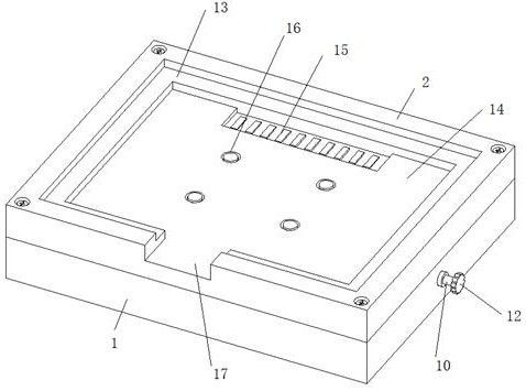
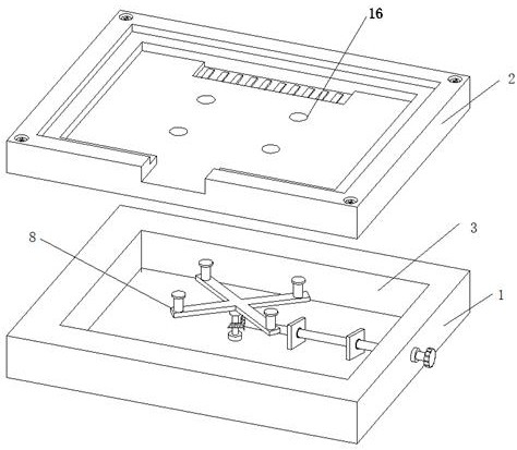
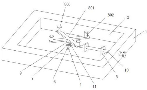
[0029] A liquid crystal display full-fit fixture for a fertilizer applicator, such as figure 1 and figure 2 As shown, including the base 1 and the jig body 2, the upper end surface of the base 1 is provided with a square groove 3, the bottom center of the square groove 3 is fixed with a bearing seat 4 and a bearing frame 5, and the upper end of the bearing seat 4 is rotatably installed with a The first rotating shaft 6, the outer wall of the middle part of the first rotating shaft 6 is fixed with a driven gear 7, the outer wall of the top of the first rotating shaft 6 is provided with a thread groove and a screw sleeve 9 is threadedly installed, and the top of the screw sleeve 9 is fixed with a jacking assembly 8; Bearing frame 5 is equipped with second rotating shaft 10, and the left end of second rotating shaft 10 is fixed with driving gear 11, and driving gear 11 and driven gear 7 are bevel gears and are connected by meshing between them, the right end of second rotating s...

Embodiment 2

[0033] On the basis of Example 1, such as Figure 4 As shown, the jacking assembly 8 also includes return springs 804. The number of return springs 804 is four and their bottom ends are respectively fixed on the middle positions of the upper end faces of the four horizontal rods. The top ends of the return springs 804 are all fixed on the jig body 2's lower end face.

[0034] In this embodiment, the return spring 804 is squeezed when the jacking assembly 8 rises, which can prevent the horizontal frame 801 from hitting the jig body 2. When the jacking assembly 8 descends, the return spring 804 has a rebound force, thereby preventing the jacking Component 8 is stuck when moving down.

Embodiment 3

[0036] On the basis of Example 2, such as Figure 5 As shown, a handle groove 18 is provided on the left side wall of the base 1, and a handle mounting seat 19 is installed in rotation inside the handle groove 18, and an arc-shaped handle 20 is mounted on the handle mounting seat 19.

[0037] In this embodiment, when the jig needs to be moved, the arc-shaped handle 20 can be rotated out, and the hand-held handle 20 can be carried and transferred. When the jig is attached, the arc-shaped handle 20 can be stored inside the handle groove 18 , taking up no space.


PUM


Abstract

The invention relates to the technical field of full-lamination jigs, in particular to a liquid crystal display screen full-lamination jig for a fertilizer applicator. The liquid crystal display screen full-lamination jig comprises a base and a jig body, a square groove is formed in the upper end surface of the base, a bearing seat and a bearing frame are fixed in the center of the bottom of the square groove, and a first rotating shaft is rotatably mounted at the upper end of the bearing seat, a driven gear is fixed to the outer wall of the middle of the first rotating shaft, a threaded groove is formed in the outer wall of the top end of the first rotating shaft, and a threaded sleeve is installed in a threaded mode, and a jacking assembly is fixed to the top end of the threaded sleeve;the jig body is fixedly installed at the upper end of the base, a touch screen placing groove is formed in the upper surface of the jig body, a liquid crystal module placing groove is formed in the bottom surface of the touch screen placing groove, and a wire arranging groove is formed in the bottom surface of the liquid crystal module placing groove. According to the invention, a product after full lamination is conveniently ejected out, the product is prevented from being clamped in the placing groove, and the operation is simple, convenient and practical.

Description

technical field [0001] The invention relates to the technical field of fully laminating fixtures, in particular to a liquid crystal display fully laminating fixture for a fertilizer applicator. Background technique [0002] The touch screen is an inductive liquid crystal display device that can receive input signals such as contacts. When the graphic buttons on the screen are touched, the tactile feedback system on the screen can drive various linking devices according to pre-programmed programs, which can be used to replace mechanical devices. The button panel of the style is adopted, and the vivid audio-visual effect is produced by the liquid crystal display screen. As the latest computer input device, the touch screen is a simple, convenient and natural way of human-computer interaction. It endows multimedia with a new look and is a very attractive new multimedia interactive device. Mainly used in public information query, industrial control, military command, electroni...

Claims


Application Information

Patent Timeline
Patent Type & Authority Applications(China)
IPC IPC(8): G02F1/13G02F1/1333
CPCG02F1/1303G02F1/13338
Inventor 贾广超
Owner 安徽金丰机械股份有限公司
Why Eureka
Try Eureka