Target detection result optimization method and system
What is AI technical title?
AI technical title is built by PatSnap AI team. It summarizes the technical point description of the patent document.
A target detection and optimization method technology, applied in the field of image recognition, can solve problems such as inaccurate detection results and display confusion
Pending Publication Date: 2021-03-16
CHINA CITIC BANK
View PDF3 Cites 0 Cited by
Summary
Abstract
Description
Claims
Application Information
AI Technical Summary
This helps you quickly interpret patents by identifying the three key elements:
Problems solved by technology
Method used
Benefits of technology
Problems solved by technology
[0005] The embodiment of the present application provides a method and system for optimizing target detection results, which solves the technical problem in the prior art that there are multiple detection frames corresponding to the detection of the same target, and the display is confusing, which leads to inaccurate detection results.
Method used
Image
Click on the blue label to locate the original text in one second.
Reading with bidirectional positioning of images and text.
Examples
Embodiment 1
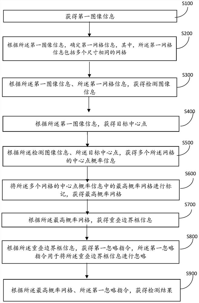
[0057] figure 1 It is a schematicflow chart of a method for optimizing target detection results according to the embodiment of the present application, such as figure 1 As shown, the embodiment of the present application provides a method for optimizing target detection results, the method comprising:
[0058] Step S100: Obtain first image information.
[0059] Further, before obtaining the first image information, the method includes: obtaining a first object category according to the first image information; and obtaining a first detection model according to the first object category.
[0060] Specifically, according to the image information to be detected, that is, the first image information, the type of the detection target is determined, and different types correspond to respective detection models, and the first image information is input into the corresponding detection models for detection. For example, if the detection target is a car, the car in the first image i...
Embodiment 2
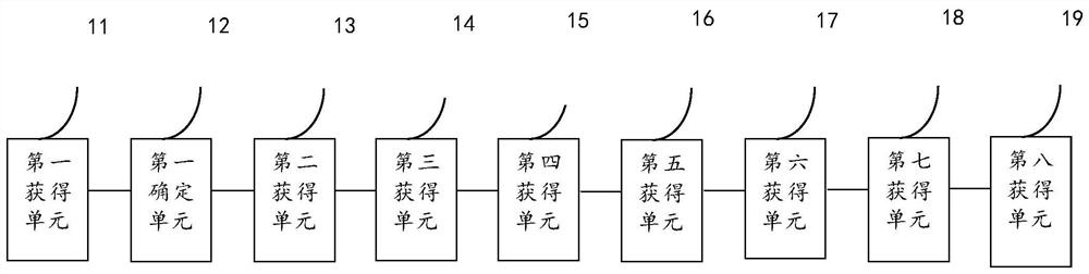
[0084] Based on the same inventive idea as the target detection result optimization method in the foregoing embodiments, the present invention also provides a target detection result optimization system, such as figure 2 As shown, the system includes:
[0085] A first obtaining unit 11, the first obtaining unit 11 is configured to obtain first image information;
[0086] A first determining unit 12, configured to determine first grid information according to the first image information, wherein the first grid information includes a plurality of grids with the same size;
[0087] A second obtaining unit 13, the second obtaining unit 13 is configured to obtain detection image information according to the first image information and the first grid information;
[0088] A third obtaining unit 14, the third obtaining unit 14 is configured to obtain the target center point according to the first image information;
[0089] A fourth obtaining unit 15, the fourth obtaining unit 15 ...
PUM
Abstract
The invention discloses a target detection result optimization method and system, and the method comprises the steps: obtaining first image information, and determining that the first grid informationcomprises a plurality of grids with the same size; obtaining detection image information according to the first image information and the first grid information; obtaining a target center point according to the first image information; obtaining central point probability information of a plurality of grids; marking the highest probability grid in the central point probability information of the plurality of grids to obtain the highest probability grid; obtaining overlapped bounding box information according to the highest probability grid; neglecting the overlapped bounding box information; and obtaining a detection result according to the neglecting instruction and the highest probability grid. The technical problem that in the prior art, a plurality of detection frames are correspondingly displayed for detecting the same target, display is disordered, and consequently the detection result is inaccurate is solved. The technical effects of realizing accurate detection of the object and better displaying the orientation of the object by clearing the similar bounding boxes are achieved.
Description
technical field [0001] The invention relates to the technical field of image recognition, in particular to a method and system for optimizing a target detection result. Background technique [0002] Image recognition refers to the technology of using computers to process, analyze and understand images to identify targets and objects in various patterns. It is a practical application of deep learning algorithms. At present, when performing target detection on images or videos, the algorithm may detect the same object multiple times, so such an algorithm does not detect an object once, but detects the same object multiple times. [0003] However, in the process of realizing the technical solution of the invention in the embodiment of the present application, the inventor of the present application found that the above-mentioned technology has at least the following technical problems: [0004] In the prior art, there is a technical problem that multiple detection frames are d...
Claims
Application Information
Patent Timeline
Application Date:The date an application was filed.
Publication Date:The date a patent or application was officially published.
First Publication Date:The earliest publication date of a patent with the same application number.
Issue Date:Publication date of the patent grant document.
PCT Entry Date:The Entry date of PCT National Phase.
Estimated Expiry Date:The statutory expiry date of a patent right according to the Patent Law, and it is the longest term of protection that the patent right can achieve without the termination of the patent right due to other reasons(Term extension factor has been taken into account ).
Invalid Date:Actual expiry date is based on effective date or publication date of legal transaction data of invalid patent.

