Slit lamp microscope and ophthalmic system
A technology of slit lamp microscope and photographing system, applied in the field of slit lamp microscope and ophthalmology system, can solve the problems of complicated lighting angles, inability to obtain good images, and long inspection time, etc.
- Summary
- Abstract
- Description
- Claims
- Application Information
AI Technical Summary
Problems solved by technology
Method used
Image
Examples
no. 1 approach 〉
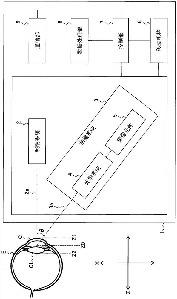
[0113] figure 1 An example of the slit lamp microscope of the first embodiment is shown in .
[0114]The slit lamp microscope 1 is used for photographing the anterior segment of the subject's eye E, and includes an illumination system 2 , an imaging system 3 , a moving mechanism 6 , a control unit 7 , a data processing unit 8 , and a communication unit 9 . In addition, reference sign C denotes a cornea, and reference sign CL denotes a lens.
[0115] The slit lamp microscope 1 may be a single device or a system including two or more devices. As an example of the latter, the slit lamp microscope 1 includes: a main unit equipped with an illumination system 2, an imaging system 3, and a moving mechanism 6; a computer equipped with a control unit 7, a data processing unit 8, and a communication unit 9; communication between communication devices. The computer may be installed together with the main device, for example, or may be installed on a network.
[0116] [Lighting System...
no. 2 approach 〉
[0212] In this embodiment, the configuration of an optical system applicable to the slit lamp microscope 1 of the first embodiment will be described. An example of this is shown in Figure 5 . In addition, except Figure 5 In addition to the set of requirements shown in , the requirements shown in other embodiments may be provided. For example, the control unit 7, the data processing unit 8, the communication unit 9, etc. of the first embodiment may be provided.
[0213] Figure 5 The lighting system 20 shown in is an example of the lighting system 2 of the first embodiment, and the left imaging system 30L and the right imaging system 30R are examples of the imaging system 3 . Reference numeral 20A denotes an optical axis (illumination optical axis) of the illumination system 20, reference numeral 30LA denotes an optical axis (left photographing optical axis) of a left imaging system 30L, and reference numeral 30Ra denotes an optical axis (right imaging optical axis) of a ...
no. 3 approach 〉
[0245] In this embodiment, the configuration of a processing system applicable to the slit lamp microscope 1 of the first embodiment will be described. In addition, in the imaging system 3 of this embodiment, for example, as described in the second embodiment Figure 5 In this way, the left imaging optical axis 30La and the right imaging optical axis 30Ra are disposed obliquely in directions opposite to each other with respect to the illumination optical axis 20a. The processing system of this embodiment performs the following artifact processing.
[0246] Figure 7 The data processing unit 8A shown in is an example of the data processing unit 8 of the first embodiment. The data processing unit 8A includes an image selection unit 81 .
[0247] The image selection unit 81 determines whether or not any of the two images acquired substantially simultaneously by the left imaging system 30L and the right imaging system 30R includes artifacts. Artifact determination includes pre...
PUM
 Abstract
Description
Claims
Application Information
 - R&D
- Intellectual Property
- Life Sciences
- Materials
- Tech Scout
- Unparalleled Data Quality
- Higher Quality Content
- 60% Fewer Hallucinations
Browse by: Latest US Patents, China's latest patents, Technical Efficacy Thesaurus, Application Domain, Technology Topic, Popular Technical Reports.
© 2025 PatSnap. All rights reserved.Legal|Privacy policy|Modern Slavery Act Transparency Statement|Sitemap|About US| Contact US: help@patsnap.com


