
An automatic cutting device for roll paper used in public toilets

A public toilet, automatic technology, applied in the directions of cleaning methods using liquids, household appliances, cleaning methods and utensils, etc., can solve the problems of waste of roll paper and low applicability, and achieve the effect of convenient placement of roll paper and improved applicability

Active Publication Date: 2022-04-08
淮北朗泰机械科技有限公司
View PDF5 Cites 0 Cited by
  • Summary
  • Abstract
  • Description
  • Claims
  • Application Information

AI Technical Summary

Problems solved by technology

[0004] In order to overcome the waste of roll paper and the shortcomings of low applicability, the technical problem of the present invention is to provide an automatic roll paper cutting device for public toilets that can automatically cut, improve the applicability of the device, and is equipped with multiple functions

Method used


Image

  • An automatic cutting device for roll paper used in public toilets
  • An automatic cutting device for roll paper used in public toilets
  • An automatic cutting device for roll paper used in public toilets

Examples


Embodiment 1

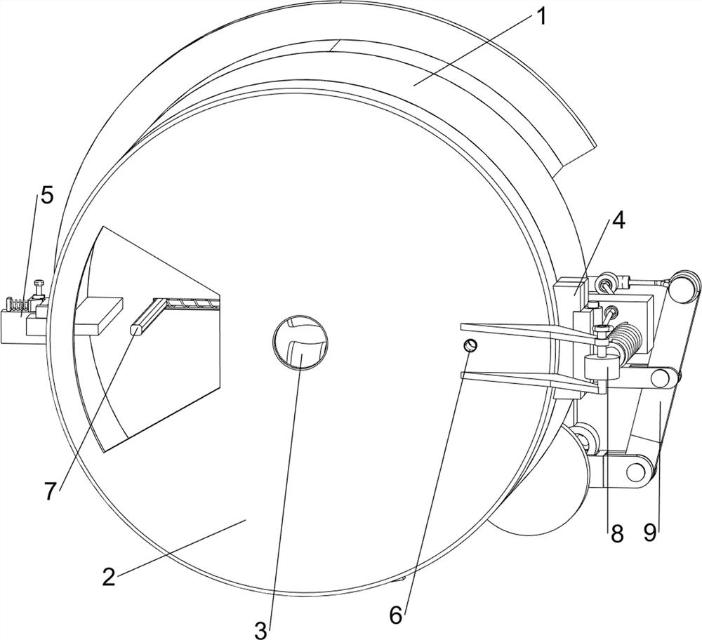
[0077] A roll paper automatic cutting device for public toilets, such as figure 1 As shown, it includes a shell 1, a set top shell 2, a cutting mechanism 3 and a connecting mechanism 4. The front side of the shell 1 is provided with a set top shell 2, and the inside of the set top shell 2 is rotatably connected with a cutting mechanism 3. The shell 1 and the set top shell A connecting mechanism 4 is connected between the 2 right sides.

[0078] When the device needs to be used, the user can rotate the top casing 2 forward, and the top casing 2 rotates forward to drive the connecting mechanism 4 to rotate forward. At this time, the user can place the roll paper in the shell 1, and the roll paper passes through the cutting mechanism 3 Protruding from the shell 1, when the roll paper is pulled, the cutting mechanism 3 will rotate forward and move down to achieve the purpose of clamping the roll paper and cutting it. At this time, the cutting mechanism 3 is compressed. When the ro...

Embodiment 2

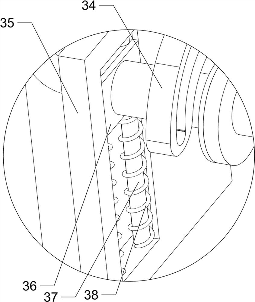
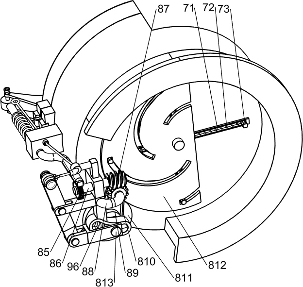
[0080] On the basis of Example 1, such as figure 2 and image 3 As shown, the cutting mechanism 3 includes a first rotating shaft 31, a contact roller 32, a first connecting rod 33, an arc guide frame 34, a support frame 35, a first slider 36, a first guide rod 37, a first spring 38, The second slide block 39 and the fifth spring 310 are slidably connected with the second slide block 39 on the set top case 2, and the second slide block 39 and the set top case 2 are all rotatably connected with the first rotating shaft 31, and the set top case 2 is wound with a fifth spring 310, the first rotating shaft 31 is connected with a contact roller 32, the upper first rotating shaft 31 is connected with a first connecting rod 33, the first connecting rod 33 is located on the right side of the contact roller 32, the top case 2 The rear side is connected with an arc-shaped guide frame 34, and the first connecting rod 33 is slidably connected with the arc-shaped guide frame 34. The rear...


PUM


Abstract

The invention relates to a cutting device, in particular to an automatic cutting device for roll paper used in public toilets. The purpose of the present invention is to provide an automatic cutting device for roll paper used in public toilets, which can automatically cut, improve the applicability of the device, and is equipped with multiple functions. The technical solution of the present invention is: an automatic roll paper cutting device for public toilets, comprising: a top case, a top case is provided on one side of the shell; a cutting mechanism, a cutting mechanism is rotatably connected inside the top case; a connecting mechanism , a connection mechanism is connected between the shell and one side of the top shell. The present invention achieves the purpose of clamping and cutting the roll paper through the cooperation of the first rotating shaft, the contact roller, the first connecting rod and the first slide block.

Description

technical field [0001] The invention relates to a cutting device, in particular to an automatic cutting device for roll paper used in public toilets. Background technique [0002] The toilet in the city is a necessary part of the urban infrastructure, which can facilitate people's life and meet the needs of physiological functions. It is the main place and facility for collecting, storing and initially treating urban excrement. As an urban building, the public toilet facility itself is one of the cultural landscapes. , Public toilets are a kind of cultural symbol of the society. No matter the attitude towards toilets, the way of using them, or the architectural design, they all reflect the customs and ethical standards of different countries and nations. From a simple and casual place for physiological metabolism, to multiple functions such as physiological metabolism, sanitation, rest, aesthetics, commerce, and culture, it essentially constitutes the transformation and prog...

Claims


Application Information

Patent Timeline
Patent Type & Authority Patents(China)
IPC IPC(8): A47K10/36B08B3/02
CPCA47K10/36B08B3/02A47K2010/3675
Inventor 刘连优
Owner 淮北朗泰机械科技有限公司
Learn More