
Communication engineering capacitor clamping device

A clamping device and communication engineering technology, which is applied in the direction of capacitors, friction-clamped detachable fasteners, electrical components, etc., can solve communication engineering capacitor noise pollution, poor clamping and fixing effect of capacitors, and large use limitations, etc. Problems, to achieve the effect of improving fluency, good effect, and improving protection

Pending Publication Date: 2021-10-26
国维技术有限公司
View PDF5 Cites 0 Cited by
  • Summary
  • Abstract
  • Description
  • Claims
  • Application Information

AI Technical Summary

Problems solved by technology

[0003] In the communication engineering system, especially in the EHVDC transmission system, a large number of high-voltage capacitors are used. In the EHVDC transmission system, there are a large number of harmonics. When the harmonic current flows through the communication engineering capacitor, the inside of the communication engineering capacitor Electrodes and insulating materials are affected by the distorted electric field generated by harmonics and vibrate. However, the existing communication engineering capacitor clamping tooling has a poor clamping and fixing effect on capacitors, resulting in the overall communication engineering capacitors vibrating at the same time. Communication engineering capacitors Vibration will not only produce noise pollution, but also affect its work quality, and the existing communication engineering capacitor clamping tooling still has the problems of fixed structure and large use limitations

Method used


Image

  • Communication engineering capacitor clamping device
  • Communication engineering capacitor clamping device
  • Communication engineering capacitor clamping device

Examples


Embodiment Construction

[0022] The present invention will be further described below in conjunction with the accompanying drawings and embodiments.

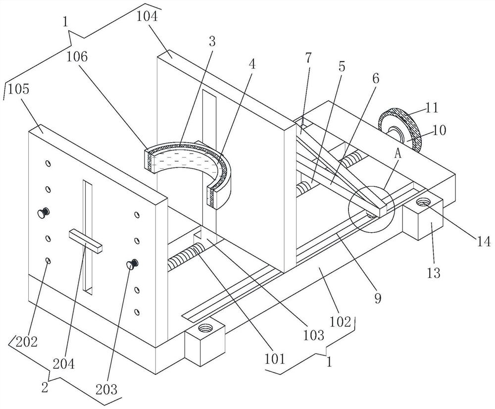
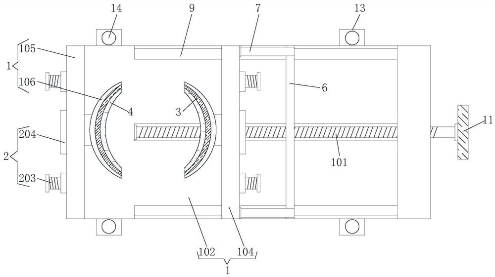
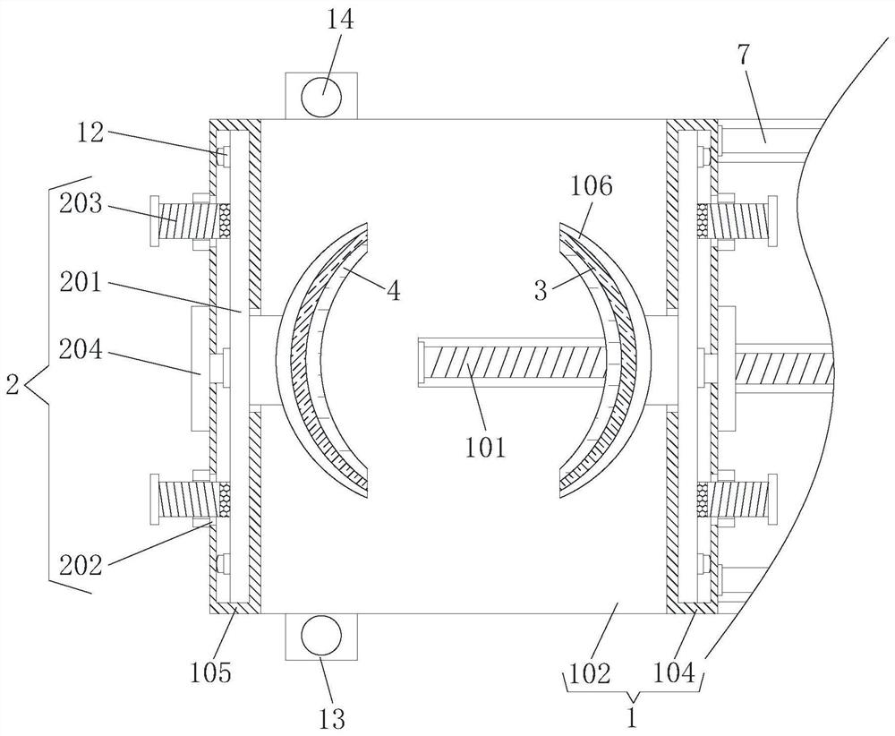
[0023] Please refer to figure 1 , figure 2 , image 3 and Figure 4 ,in figure 1 It is a structural schematic diagram of the present invention;

[0024] figure 2 It is a top view of the structure of the present invention; image 3 It is a top sectional view of a partial structure of the present invention; Figure 4 for the invention figure 1 The enlarged schematic diagram of the structure at A in the center is a capacitor clamping device for communication engineering, including a clamping mechanism 1 and an adjusting mechanism 2. The clamping mechanism 1 includes a threaded rod 101, a bottom plate 102, a threaded block 103, a clamping plate 104, and a vertical plate 105 and clamp hoop 106, one end of threaded rod 101 is rotatably connected with base plate 102; Vertical plate 105, one side of vertical plate 105 and clamping plate 104 are all p...


PUM


Abstract

The invention provides a communication engineering capacitor clamping device. The communication engineering capacitor clamping device comprises a clamping mechanism and an adjusting mechanism, the clamping mechanism comprises a threaded rod, a bottom plate, a threaded block, a clamping plate, a vertical plate and a clamping hoop, one end of the threaded rod is rotatably connected with the bottom plate, the outer side of the threaded rod is in threaded connection with the threaded block, and the top of the threaded block is fixedly connected with the clamping plate. The vertical plate is fixedly connected to the top of the bottom plate, and clamping hoops are arranged on one side of the vertical plate and one side of the clamping plate; the adjusting mechanism comprises an adjusting rod, a fixing hole, a fixing bolt and an adjusting block; according to the communication engineering capacitor clamping device, the clamping plate is driven by the threaded block to move, the clamping plate moves to drive the clamping hoop on one side of the clamping plate to move, and after the clamping plate moves to the clamping position, the clamping plate is matched with the clamping hoop on one side of the vertical plate to clamp and fix a capacitor, so that the purpose of clamping and fixing the communication engineering capacitor is achieved, the clamping and fixing effect is good. The vibration amplitude of the communication engineering capacitor in use can be effectively reduced, and the service life of the capacitor is prolonged.

Description

technical field [0001] The invention relates to the field of communication engineering equipment, in particular to a communication engineering capacitance clamping device. Background technique [0002] Communication engineering capacitors are capacitors used in the field of communication engineering. They are also reactive power compensation devices. Circuit breaker capacitors, electric heating capacitors, pulse capacitors, DC and filter capacitors and standard capacitors, etc. [0003] In the communication engineering system, especially in the EHVDC transmission system, a large number of high-voltage capacitors are used. In the EHVDC transmission system, there are a large number of harmonics. When the harmonic current flows through the communication engineering capacitor, the inside of the communication engineering capacitor Electrodes and insulating materials are affected by the distorted electric field generated by harmonics and vibrate. However, the existing communicati...

Claims


Application Information

Patent Timeline
IPC IPC(8): F16B2/12H01G2/04
CPCF16B2/12H01G2/04
Inventor 叶元元孙勇张正伟刘元高光冬
Owner 国维技术有限公司
Learn More