Wireless communication module test system

A technology of wireless communication module and testing system, which is applied in wireless communication, transmission system, digital transmission system, etc. It can solve the problems of inability to clamp and use heat dissipation effect, inconvenient detection of signal receiving sensitivity, etc., and achieve the convenience of testing status and viewing Effect

Pending Publication Date: 2021-09-24
深圳市宏杰兴业科技有限公司
View PDF5 Cites 0 Cited by
  • Summary
  • Abstract
  • Description
  • Claims
  • Application Information

AI Technical Summary

Problems solved by technology

[0005] In view of the above-mentioned shortcomings and deficiencies of the prior art, the present invention provides a wireless communication module testing system, which solves the technical problems of inconvenient detection of signals and weak receiving sensitivity, inability to clamp and use, and poor heat dissipation

Method used


Image

  • Wireless communication module test system
  • Wireless communication module test system
  • Wireless communication module test system

Examples


Embodiment 1

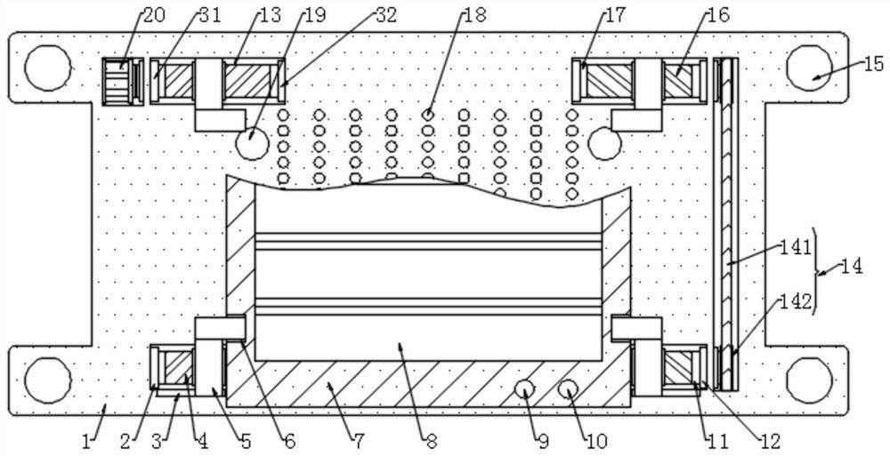
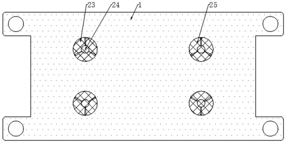
[0039] refer to figure 1 , figure 2 , image 3 and Figure 5 First, take the wireless controller 7, insert the positioning column 26 into the positioning groove 19 for preliminary fixing, then control the driving motor 20 to work through the external controller, and drive the positive thread column 4 and the reverse thread column 16 through the first rotating shaft 31 Rotate, and drive the gear 142 to rotate through the second rotating shaft 11, by means of the transmission effect of the tooth chain 141, drive another reverse thread post 16 and the positive thread post 4 to rotate through another gear 142 and another second rotating shaft 11, so that the limit block 5. Move in the direction of the wireless controller 7 until the limit block 5 is snapped into the limit groove 6, clamp and fix the wireless controller 7 again, and then the fan 24 and the semiconductor refrigerator 22 can be controlled to work through the external controller. After the external air is cooled, ...

Embodiment 2

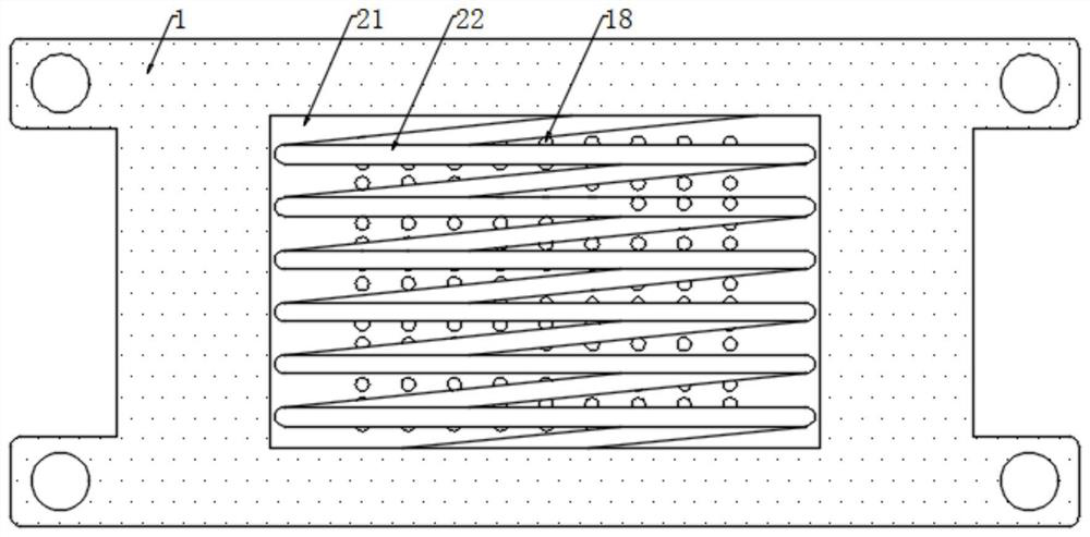
[0041] refer to figure 1 and Figure 4 , during the testing process, the external equipment transmits information, and the wireless communication module 27 transmits the transmission data to the signal strength detection module 28 and the receiving sensitivity detection module 29 for classification, and then sends the classified data to the data processing center 30 respectively, and then through The analysis module 301 sends the data analysis and processing to the comparison module 302 for comparison with the set value, and sends the comparison data to the database 303 for storage, so that it can be viewed later. When it matches the set value, the data processing center 30 controls The green second warning light 10 lights up to indicate normal. When the set value is not met, the red first warning light 9 is controlled to light up to indicate that there is a problem, and the signal strength and receiving sensitivity are displayed linearly through the display screen 8 for easy ...


PUM


Abstract

The invention relates to a wireless communication module test system which comprises a mounting plate, two grooves are formed in the front side of the mounting plate, a first bearing and a third bearing are fixedly connected to the left side face and the middle of the inner wall of each groove respectively, and a first rotating shaft and a third rotating shaft are arranged in the first bearing and the third bearing in a penetrating mode respectively. A right-hand threaded column is fixedly connected between the first rotating shaft and the third rotating shaft. Compared with the prior art, the wireless communication module test system has the beneficial effects that the analysis module, the comparison module and the database are adopted, so that compared with the prior art, the wireless communication module test system can analyze signal strength and transmission sensitivity and compare analysis data with set data through the comparison module, and the test purpose is achieved. Due to the fact that the draught fan and the semiconductor cooler are adopted to work, external air can be refrigerated through the semiconductor cooler and then conveyed to the wireless controller through the heat dissipation holes, and the purpose of conducting heat dissipation on the wireless controller is achieved.

Description

technical field [0001] The invention relates to the technical field of wireless communication module testing, in particular to a wireless communication module testing system. Background technique [0002] Wireless communication refers to long-distance transmission communication between multiple nodes without transmission through conductors or cables. Wireless communication can be carried out by using radios, radios, etc. Wireless communications include a variety of fixed, mobile and portable applications. [0003] Most of the existing wireless communication devices will have problems of weak signal and low receiving sensitivity after long-term use. When this problem occurs, it will affect the user's use. At the same time, the user cannot test it in time to determine the problem, which is extremely inconvenient to use. ; At the same time, most of the existing wireless communication module test devices can not be clamped when in use, and then need to be hand-held during use, ...

Claims


Application Information

Patent Timeline
IPC IPC(8): H04W24/08H04B17/309H04B17/318H04Q1/02H04Q1/04H04L12/26
CPCH04W24/08H04B17/309H04B17/318H04Q1/035H04Q1/04H04L43/04Y02D30/70
Inventor 陈景林朱金文温利冰
Owner 深圳市宏杰兴业科技有限公司
Why Eureka
Try Eureka