Small machining tool cleaning equipment for machinery factory

A technology for mechanical processing and cleaning equipment, which is applied to mechanical equipment, cleaning methods using tools, machines/engines, etc. It can solve the problems of inconvenient cleaning of mechanical processing tools and achieve a comprehensive washing effect

Inactive Publication Date: 2021-03-19
苏州斯睿研智能科技有限公司
View PDF9 Cites 3 Cited by
  • Summary
  • Abstract
  • Description
  • Claims
  • Application Information

AI Technical Summary

Problems solved by technology

[0004] The purpose of the present invention is to solve the problem that the mechanical processing tools in the prior art are not easy to clean, and propose a small-scale mechanical processing tool cleaning equipment for machinery factories

Method used


Image

  • Small machining tool cleaning equipment for machinery factory
  • Small machining tool cleaning equipment for machinery factory
  • Small machining tool cleaning equipment for machinery factory

Examples


Embodiment 1

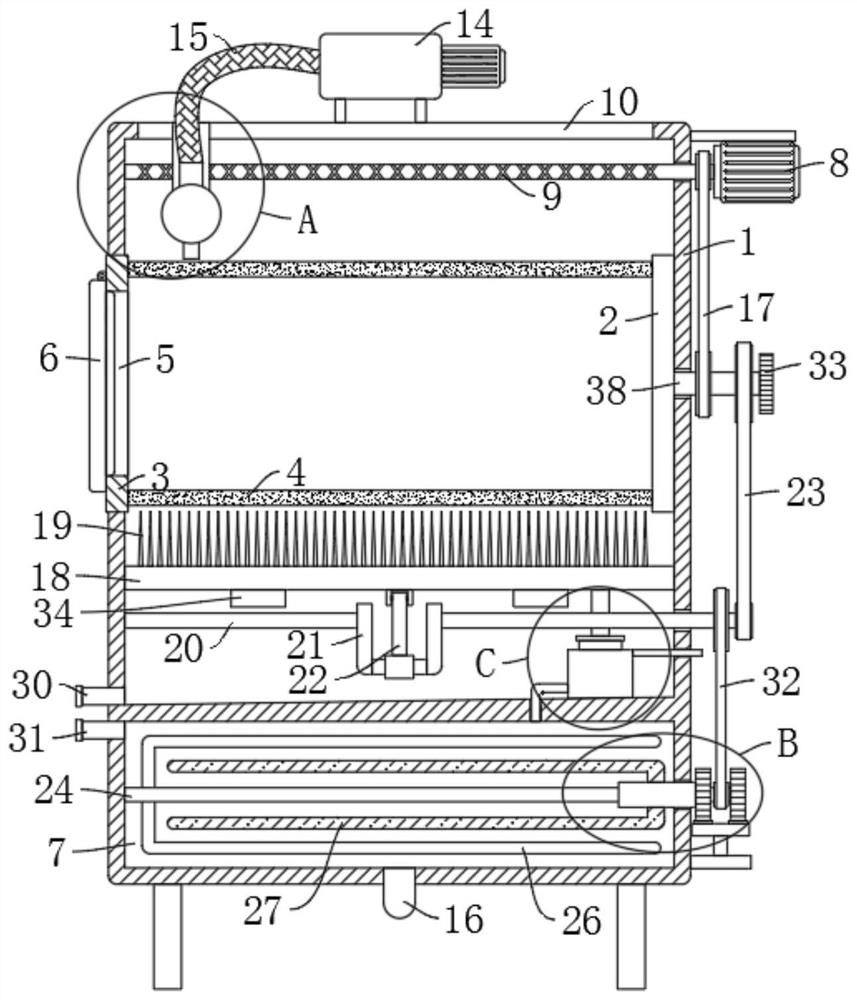
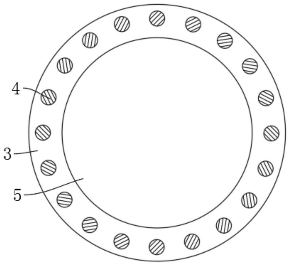
[0031] refer to Figure 1-6 , a kind of cleaning equipment for small-scale machining tools used in a machinery factory, comprising a cleaning box 1, the left and right side walls of the cleaning box 1 are respectively rotatably connected with a plurality of linearly distributed left disks 3 and right disks 2, and the left disk 3 and the right A plurality of circumferentially distributed support rods 4 are fixedly connected between the disks 2. The side wall of the left disk 3 extends to the outer wall of the cleaning box 1 and is provided with a placement groove 5. The outer wall of the placement groove 5 is rotatably equipped with an end cover 6 for cleaning. The side wall of the lower end of the box 1 is provided with a drainage pipe 30, the lower end of the cleaning box 1 is fixedly equipped with a mixing box 7, the side wall of the mixing box 7 is provided with a liquid feeding pipe 31, and the upper end of the cleaning box 1 is fixedly installed with a water pump 14, a wat...

Embodiment 2

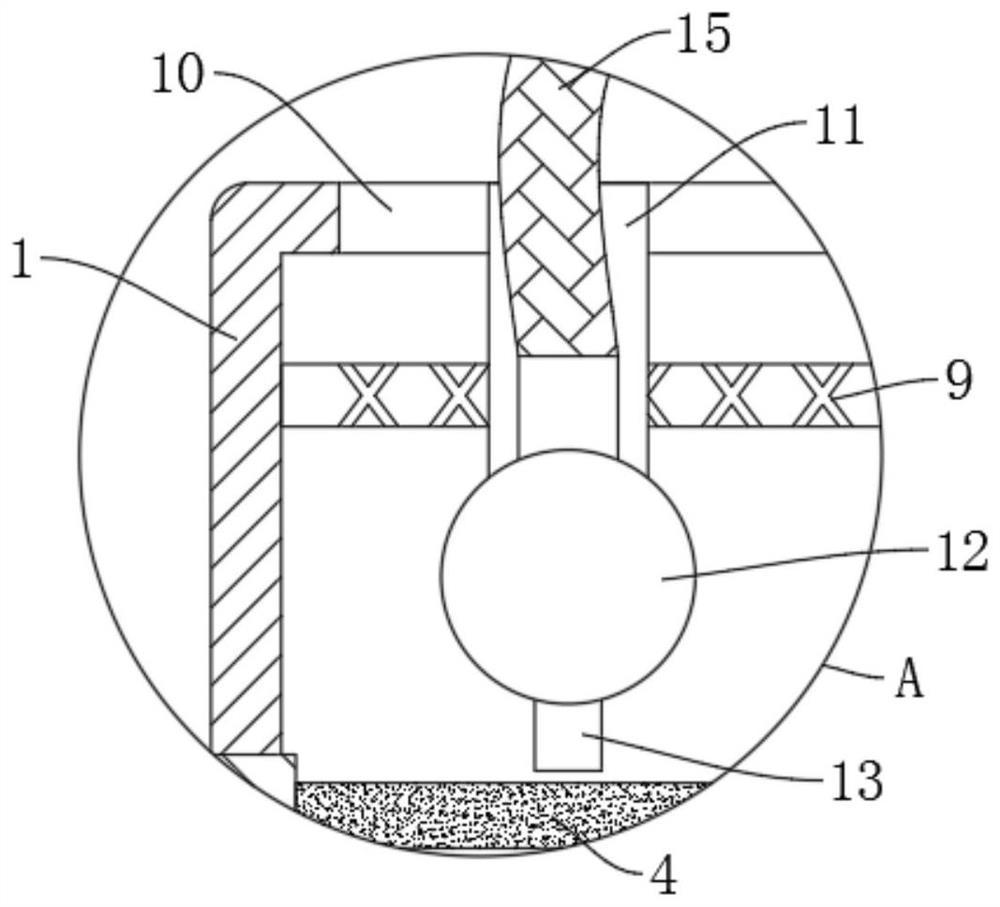
[0036] refer to figure 1 and image 3, is basically the same as Embodiment 1, furthermore: the reciprocating flushing device includes a motor 8 fixedly installed on the side wall of the cleaning box 1, and the output end of the motor 8 is fixedly connected with a reciprocating lead screw 9 extending to the top of the cleaning box 1, The outer wall of the reciprocating lead screw 9 is provided with a lead screw slider 11, the upper end of the cleaning box 1 is provided with a chute 10 cooperating with the lead screw slider 11, and the lower end of the lead screw slider 11 is fixedly connected with a transverse tube 12, and the transverse tube The lower end of 12 is fixedly equipped with a plurality of evenly distributed nozzles 13, the output pipe of the water pump 14 is fixedly connected with the horizontal pipe 12 through the telescopic hose 15, and the side walls of the plurality of right discs 2 are fixedly connected with a nozzle extending to the cleaning tank. 1 The rota...

Embodiment 3

[0038] refer to figure 1 and Figure 4 , which is basically the same as in Embodiment 1, furthermore: the strengthened cleaning device includes a plurality of linearly distributed cleaning plates 18 that are slidably connected to the bottom of the cleaning box 1, and the upper ends of the multiple cleaning plates 18 are provided with evenly distributed long hairs. Brush 19, the lower end of a plurality of cleaning plates 18 is fixedly connected by connecting plate 34, and the inner bottom side wall of cleaning box 1 is connected with rotating rod 20 in rotation, and the middle part of rotating rod 20 is fixedly equipped with crankshaft 21, and cleaning plate 18 The lower end of the connecting rod 22 is rotatably connected to the connecting rod 22, and the other end of the connecting rod 22 is rotatably connected to the outer wall of the crankshaft 21. The right end of the rotating rod 20 is connected to the rotating shaft 38 through the second chain drive 23. During flushing, ...


PUM


Abstract

The invention discloses small machining tool cleaning equipment for a machinery factory, and belongs to the technical field of machining tool cleaning equipment. The small machining tool cleaning equipment for the machinery factory comprises a cleaning box; the left side wall and the right side wall of the cleaning box are rotationally connected with a plurality of linearly-distributed left discsand right discs correspondingly; a plurality of circumferentially-distributed supporting rods are fixedly connected between the left discs and the right discs; a mixing box is fixedly installed at thelower end of the cleaning box; a water pump is fixedly installed at the upper end of the cleaning box; a water suction pipe of the water pump is fixedly connected with the lower end of the mixing box; a reciprocating flushing device matched with the water pump is arranged at the inner top of the cleaning box; a reinforced cleaning device matched with the reciprocating flushing device is arrangedat the inner bottom of the cleaning box; and an efficient mixing device is arranged in the mixing box. By means of the cleaning box in the small machining tool cleaning equipment for the machinery factory, machining tools can be conveniently and effectively cleaned, and the cleaning efficiency is higher under the action of a cleaning plate.

Description

technical field [0001] The invention relates to the technical field of cleaning equipment for machining tools, in particular to a cleaning equipment for small machining tools used in machinery factories. Background technique [0002] The machining process refers to the steps of manufacturing and processing workpieces or parts. The process of directly changing the shape, size and surface quality of the blank by using the method of machining to make it a part. [0003] Various tools are often used in the machining process. These tools will inevitably come into contact with substances such as engine oil and rough metal debris during use, and adhere to the surface of the tool under the action of the engine oil. Currently, these tools are in use Finally, most of the surface is cleaned manually, but in the factory, there are many tools used, and the efficiency of manual cleaning is relatively low, which will affect the normal use of the tools. Contents of the invention [0004]...

Claims


Application Information

Patent Timeline
Patent Type & Authority Applications(China)
IPC IPC(8): B08B3/02B08B1/00B08B3/08B08B3/10B01F7/04F04B35/04
CPCB08B3/02B08B1/002B08B3/08B08B3/102F04B35/04B01F27/702B01F27/706
Inventor 张倩
Owner 苏州斯睿研智能科技有限公司
Why Eureka
Try Eureka