Valve for dosing fluid

A fluid and valve needle technology, which is applied in the field of metering fluid valves, can solve the problems of valve characteristic changes, stopper wear, etc., achieve reliable functions, improve injection characteristics, improve configuration and working methods

Pending Publication Date: 2021-03-19
ROBERT BOSCH GMBH
View PDF1 Cites 0 Cited by
  • Summary
  • Abstract
  • Description
  • Claims
  • Application Information

AI Technical Summary

Problems solved by technology

[0003] In the configuration of the fuel injection valve known from DE 10 2016 225 776 A1, the following disadvantages can arise: a certain amount of wear occurs at the stop during the service life
As a result, a change in the valve characteristic may occur due to the stronger hydraulic damping at the stop

Method used


Image

  • Valve for dosing fluid

Examples


Embodiment Construction

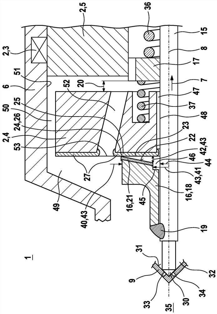
[0022] figure 1A schematic sectional view of a detail of a valve 1 for metering fluids according to a preferred embodiment is shown. In particular, valve 1 can be designed as fuel injection valve 1 . A preferred application is a fuel injection system, in which such a fuel injection valve 1 is designed as a high-pressure injection valve 1 and is used to inject fuel directly into an associated combustion chamber of an internal combustion engine. The configuration of the valve 1 is particularly suitable for liquid fluids, especially liquid fuels such as gasoline or diesel, or for liquid mixtures with at least one fuel.

[0023] The valve 1 has an electromagnetic actuator 2 comprising a solenoid coil 3 , an armature 4 and an inner pole 5 . When solenoid coil 3 is energized, the solenoid circuit is closed via housing (valve housing) 6 , armature 4 and inner pole 5 , whereby armature 4 is actuated along longitudinal axis (axis) 8 of housing 6 in opening direction 7 . The housing ...


PUM


Abstract

The invention relates to a valve (1) for dosing fluid, in particular a fuel injection valve for an internal combustion engine, comprising an actuator (2) and a valve needle (15) which can be actuatedby the actuator (2) along a longitudinal axis (8), an armature (4) of the actuator (2) being arranged on the valve needle (15), wherein the armature (4) is displaceable relative to the valve needle (15) in accordance with an armature free path (20) along the longitudinal axis (8), and wherein at least one stop element (16) arranged on the valve needle (15) is provided, said stop element (16) limiting the displacement of the armature (4) relative to the valve needle (15). According to the invention, a wear-resistant edge (24) is provided, on which wear-resistant edge a contact (26) occurs between the armature (4) and the stop element (16) during operation in order to limit the displacement of the armature (4) relative to the valve needle (15).

Description

technical field [0001] The invention relates to a valve for metering fluids, in particular a fuel injection valve for an internal combustion engine. In particular, the invention relates to the field of injectors for fuel injection systems of motor vehicles, in which injectors fuel is preferably injected directly into a combustion chamber of an internal combustion engine. Background technique [0002] A fuel injection valve for a fuel injection system of an internal combustion engine is known from DE 10 2016 225 776 A1. The known fuel injector comprises a housing, a valve needle with a valve closing body, which cooperates with a valve seat surface to form a sealing seat, and an armature of the electromagnetic actuator arranged on the valve needle. Positionally fixed stops are arranged on the valve needle, between which the armature can move corresponding to the free-form travel of the armature. Such a stop can be formed on a stop element connected to the valve needle. [0...

Claims


Application Information

Patent Timeline
Patent Type & Authority Applications(China)
IPC IPC(8): F02M51/06F02M61/10
CPCF02M51/0614F02M51/066F02M61/12F02M61/10F02M51/0685F02M61/166F02M61/20
Inventor M·比纳N·赫尔曼P·劳申贝格尔S·塞尔尼
Owner ROBERT BOSCH GMBH
Why Eureka
Try Eureka