Small in-bore environment-sensitive mechanism

An internal environment and sensitive technology, applied in the field of fuze, to achieve the effect of reducing the axial size

Pending Publication Date: 2021-03-19
XIAN ELECTRO MECHANICAL INFORMATION INST
View PDF11 Cites 7 Cited by
  • Summary
  • Abstract
  • Description
  • Claims
  • Application Information

AI Technical Summary

Problems solved by technology

[0003] The purpose of the present invention is to propose a low-overload in-bore firing mechanism without solving the problem of how to effectively realize activation in a miniaturized device when the launch overload is lower than the drop overload in a low-launch overload environment.

Method used


Image

  • Small in-bore environment-sensitive mechanism
  • Small in-bore environment-sensitive mechanism
  • Small in-bore environment-sensitive mechanism

Examples


Embodiment Construction

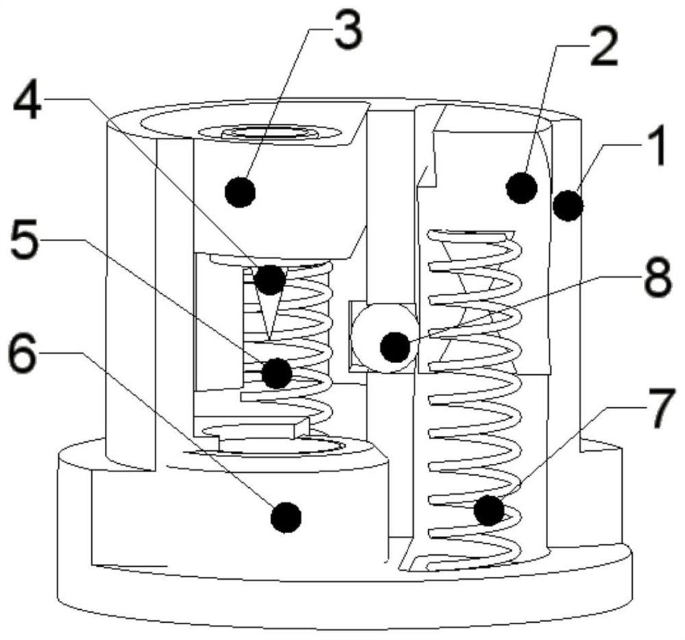
[0026] The low-overload in-bore ignition mechanism in this embodiment, as attached figure 1 , mainly includes: base 1, inertia block 2, firing pin seat 3, firing pin 4, firing pin spring 5, acupuncture cap 6, inertia block spring 7, steel ball 8.

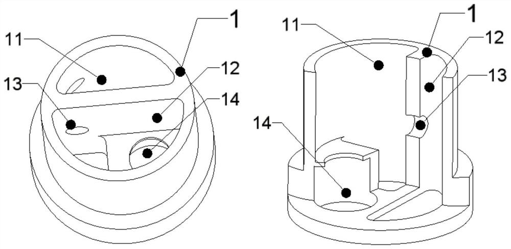
[0027] The base 1 is as attached figure 2 , the shape is a structure of revolution, and there are two semi-cylindrical cavities axially penetrating inside. The first semi-cylindrical cavity 11 is used to install the inertial mass 2 and constrain the inertial mass 2 to move axially in the cavity 11 . The second semi-cylindrical cavity 12 is used for installing the firing pin seat 3 and constraining the axial movement of the firing pin seat 3 in the cavity 12 . The radial through hole 13 is used to install the steel ball 8, and the radial through hole 13 communicates with the first semi-cylindrical cavity 11 and the second semi-cylindrical cavity 12;

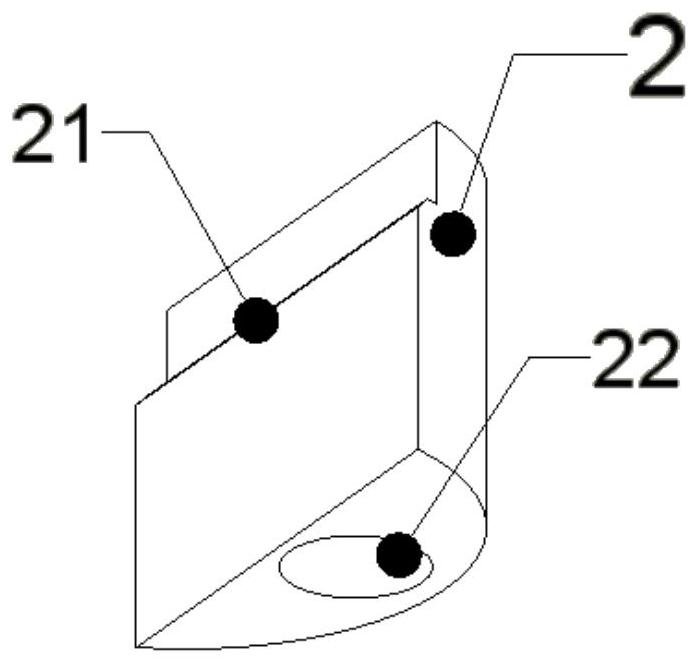
[0028] The inertial block 2 is as attached image 3 , is a semi-cylindrical st...


PUM


Abstract

The invention discloses a small in-bore environment-sensitive mechanism. According to the invention, under falling overload, movement generated by stress of a firing pin seat 3 in a falling process isisolated through constraint of an inertia block 2 on the firing pin seat 3 when the inertia block 2 moves downwards in the falling process, and the situation that the firing pin seat 3 and a firing pin 4 on the firing pin seat 3 move downwards under the falling overload to detonate a needle-punched detonator 6 is prevented. Under a long-time low-overload launching condition, the inertia block 2 moves downwards to the end and then relieves constraint on a steel ball 8, the firing pin seat 3 continues to bear a downward overload force, the steel ball 8 embedded into a groove 31 of the firing pin seat 3 is extruded into an empty cavity in a step 21 of a heavy block 2, and therefore constraint on the firing pin seat 3 is relieved, and the firing pin seat 3 continues to bear the downward overload and impacts and detonates a needle-punched cap 6. The radial size of the mechanism is reduced through the semi-cylindrical design of the inertia block and the firing pin seat which are restrainedin sequence, and the axial size is reduced through parallel installation for the inertia block and the firing pin seat and staggered layout for the firing pin and a spring. Meanwhile, the mechanism isof a sealed structure and cannot be polluted by dust in a thermal battery.

Description

technical field [0001] The invention belongs to the technical field of fuzes and is used for the activation of a device in the fuze under the firing environment in a bore. Background technique [0002] The fuze needs to activate certain devices in the environment of in-bore launch, especially the fuze power supply that provides energy for the fuze. For the launch environment with high launch overload, the launch overload is greater than the drop overload during service handling; while in the low launch overload environment, the launch overload is lower than the drop overload, and the ordinary single-degree-of-freedom spring-mass system cannot pass the lengthening spring under the premise of miniaturization. To distinguish the low launch overload environment from the drop environment during service handling. Environmentally sensitive mechanisms such as clock mechanisms and zigzag grooves that identify overload time are not easy to miniaturize and install in devices that need...

Claims


Application Information

Patent Timeline
Patent Type & Authority Applications(China)
IPC IPC(8): F42C15/21
CPCF42C15/21
Inventor 贺文赵旭刘占恒田中旺王晓霞翟蓉马红萍杨军
Owner XIAN ELECTRO MECHANICAL INFORMATION INST
Why Eureka
Try Eureka