Image position deviation compensation processing method, system and device in alignment assembly of marker lamp and lens, processor and storage medium

A technology for marking lamps and lenses, which is applied in image data processing, image analysis, image enhancement, etc., and can solve problems such as inaccurate pasting, inaccurate alignment, and deviation

Pending Publication Date: 2021-03-19
MAGNA MIRRORS (TAICANG) AUTOMOTIVE TECHNOLOGY CO LTD
View PDF1 Cites 0 Cited by
  • Summary
  • Abstract
  • Description
  • Claims
  • Application Information

AI Technical Summary

Problems solved by technology

However, in the positioning and assembly process of the warning light module, there will be practical problems such as inaccurate alignment caused by the flaws of the parts themselves, and differences in the light pattern of the driver's direction.
For example, during the lighting process of the module, if there is light leakage at the edge of the diaphragm or in the non-shape area, the calculation of the alignment will deviate, resulting in inaccurate pasting.

Method used


Image

  • Image position deviation compensation processing method, system and device in alignment assembly of marker lamp and lens, processor and storage medium
  • Image position deviation compensation processing method, system and device in alignment assembly of marker lamp and lens, processor and storage medium
  • Image position deviation compensation processing method, system and device in alignment assembly of marker lamp and lens, processor and storage medium

Examples


Embodiment Construction

[0056] In order to describe the technical content of the present invention more clearly, further description will be given below in conjunction with specific embodiments.

[0057] Before describing the embodiments according to the present invention in detail, it should be noted that in the following, relative terms such as first and second are only used to distinguish one entity or action from another entity or action, and do not necessarily require or Any actual such relationship or order between such entities or actions is implied. The terms "comprising", "comprising" or any other variant are intended to cover a non-exclusive inclusion whereby a process, method, article or apparatus comprising a set of elements includes not only those elements but also other elements not expressly listed elements, or elements inherent in such a process, method, article, or apparatus.

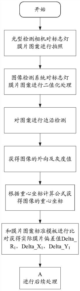
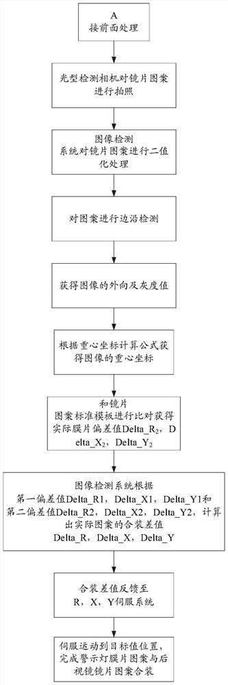
[0058] see figure 1 and figure 2 As shown, the image position deviation compensation processing method ...


PUM


Abstract

The invention relates to an image position deviation compensation processing method for achieving alignment assembly of a marker lamp diaphragm pattern and a lens pattern, which comprises the following steps of: importing marker lamp pattern and lens pattern data into an image detection system to finish template setting, and obtaining corresponding pattern contour information after photographing processing, and calculating a corresponding gravity center coordinate value and a deviation value, and taking the coordinate difference value compensation amount and the deviation angle difference value compensation amount as a combination difference value of an actual pattern so as to complete combination of the pattern. The invention further relates to a control method, system and device based onthe method, a processor and a computer readable storage medium. By the adoption of the corresponding method, system and device, the processor and the computer readable storage medium, when the warning lamp module is in a non-lighting state, the image equipment collects the position of the warning lamp module and determines the pattern position of the rearview mirror lens through secondary photographing, and the warning lamp module is prevented from inclining relative to the pattern of the rearview mirror lens.

Description

technical field [0001] The present invention relates to the field of vehicle accessories, in particular to a rearview mirror blind zone warning light, specifically a method for compensating image position deviation for realizing alignment assembly of a sign light diaphragm pattern and a lens pattern and assembling the corresponding warning light module to A control method, system, device, processor and computer-readable storage medium for rearview mirror lenses. Background technique [0002] There is usually a visual blind spot in the vehicle rearview mirror, and the driver cannot see the vehicle in the blind spot. If there is an overtaking vehicle in the blind spot, a collision accident will occur when changing lanes at this time. In harsh environments such as thunderstorms, heavy fog, and dim light at night, it is more difficult for the driver to see the vehicles behind, and at this time, changing lanes is more dangerous. In order to solve the visual blind spot of the rea...

Claims


Application Information

Patent Timeline
Patent Type & Authority Applications(China)
IPC IPC(8): G06T7/00G06T7/66
CPCG06T7/001G06T2207/10004G06T2207/30108G06T7/66
Inventor 吴骏陈钰陆申钢
Owner MAGNA MIRRORS (TAICANG) AUTOMOTIVE TECHNOLOGY CO LTD
Why Eureka
Try Eureka