Thermal management system for electrically powered vehicle

A technology of thermal management system and system controller, applied in the field of thermal management system

Pending Publication Date: 2021-03-19
FORD GLOBAL TECH LLC +1
View PDF0 Cites 1 Cited by
  • Summary
  • Abstract
  • Description
  • Claims
  • Application Information

AI Technical Summary

Problems solved by technology

Managing heat transfer between different sets of components in an electrified vehicle without adding expensive heat exchangers and / or multiple valve systems is challenging

Method used


Image

  • Thermal management system for electrically powered vehicle
  • Thermal management system for electrically powered vehicle
  • Thermal management system for electrically powered vehicle

Examples


Embodiment Construction

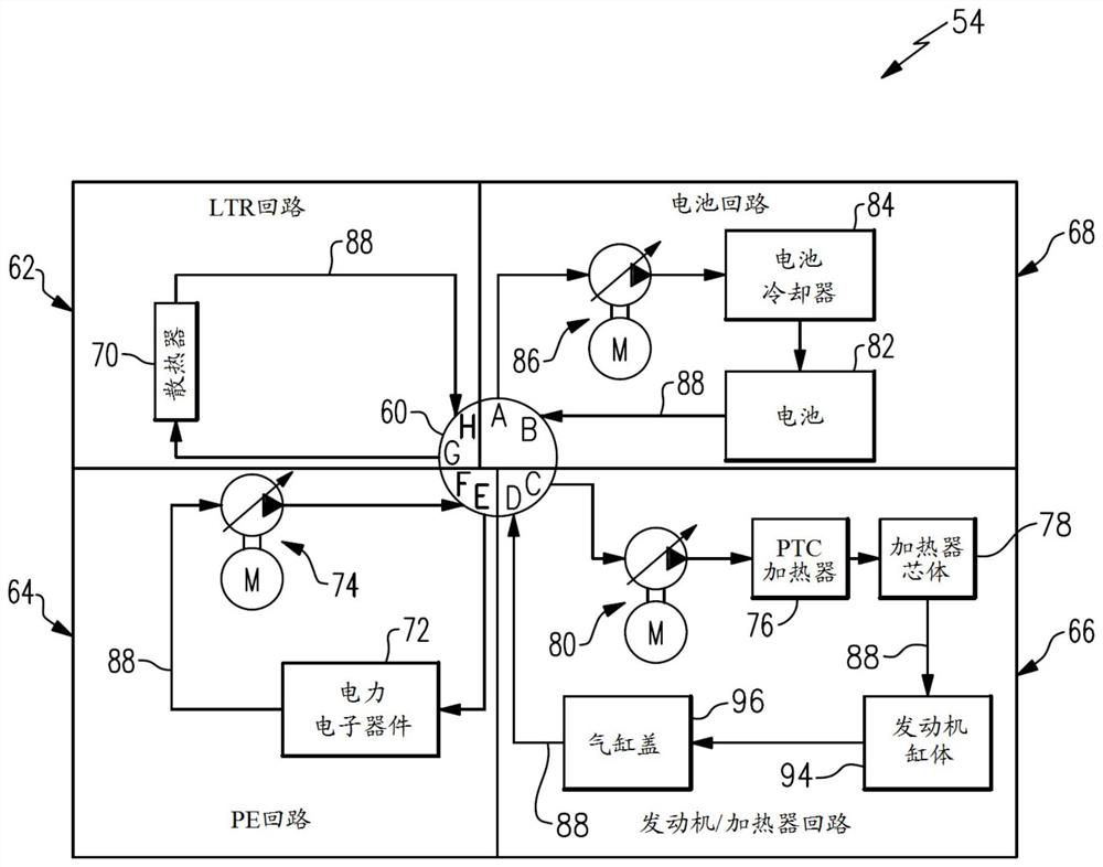
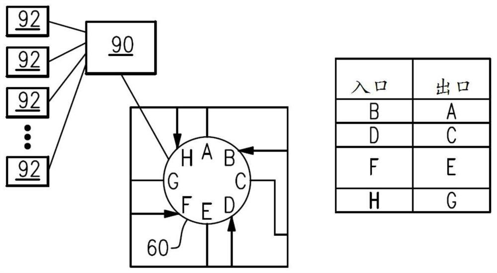
[0046] The present disclosure details a thermal management system for an electrified vehicle. An exemplary thermal management system may utilize a single valve to connect together one or more of the radiator loop, power electronics loop, heater loop, and battery loop, and may also be configured to connect the radiator loop, At least one of the power electronics loop, the heater loop, and the battery loop is isolated from any remaining of the radiator loop, the power electronics loop, the heater loop, and the battery loop.

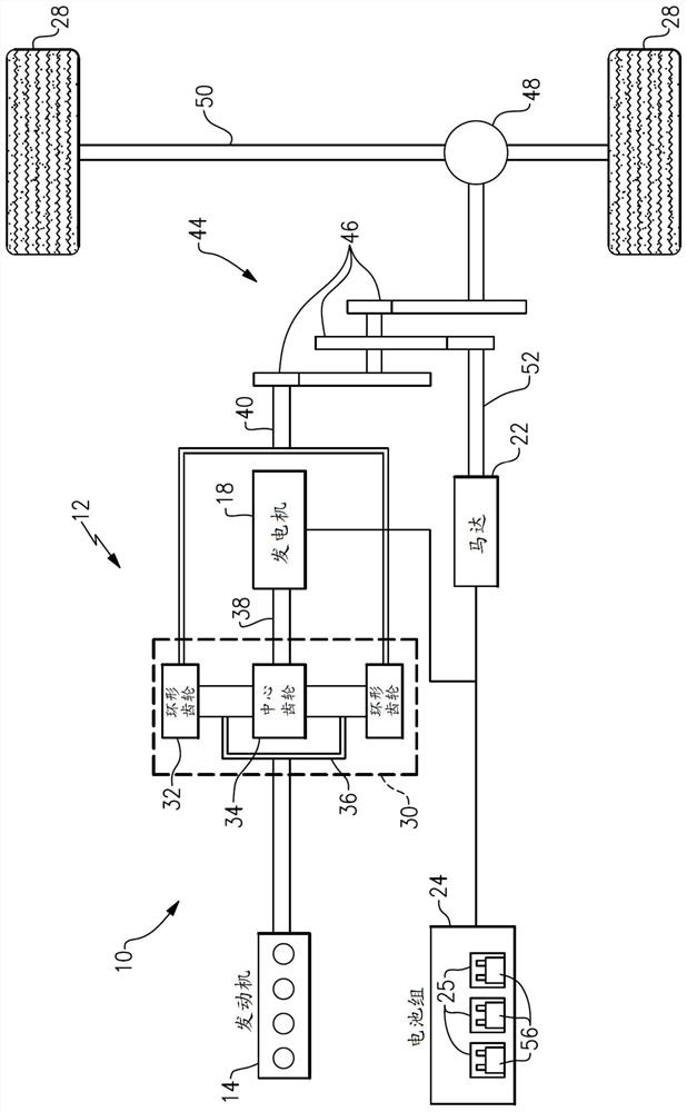
[0047] figure 1 A powertrain 10 for an electrified vehicle 12 is schematically shown. Although depicted as a hybrid electric vehicle (HEV), it should be understood that the concepts described herein are not limited to HEVs and may be extended to other electrified vehicles, including but not limited to plug-in hybrid electric vehicles (PHEVs), battery electric vehicles (BEV), fuel cell vehicles, etc.

[0048] In one embodiment, the powertrain 10 is a powe...


PUM


Abstract

The present disclosure provides a thermal management system for an electrically powered vehicle. An example thermal management system, in particular, includes a valve; a heat sink circuit configured to be connected to the valve; a power electronics circuit configured to be connected to the valve; a heater circuit configured to be connected to the valve; and a battery circuit configured to be connected to the valve. And the valve is configured to connect one or more of the heat sink circuit, the power electronics circuit, the heater circuit, and the battery circuit together, and the valve is configured to isolate at least one of the heat sink circuit, the power electronics circuit, the heater circuit, and the battery circuit from any remaining circuits of the heat sink circuit, the power electronics circuit, the heater circuit, and the battery circuit.

Description

technical field [0001] The present disclosure relates to a thermal management system for an electrified vehicle. Background technique [0002] An electrified vehicle includes a high voltage traction battery pack that powers the electric vehicle's electric motor and other electrical loads. Managing heat transfer between different sets of components in an electrified vehicle without adding expensive heat exchangers and / or multiple valve systems is challenging. Contents of the invention [0003] A thermal management system according to an exemplary aspect of the present disclosure comprises, inter alia: a valve; a radiator circuit configured to be connected to the valve; a power electronics circuit configured to connected to the valve; a heater circuit configured to be connected to the valve; and a battery circuit configured to be connected to the valve. The valve is configured to connect together one or more of the radiator circuit, the power electronics circuit, the heate...

Claims


Application Information

Patent Timeline
IPC IPC(8): H01M10/613H01M10/615H01M10/625H01M10/6556H01M10/6568H01M10/6571H01M10/667H01M10/663B60L58/26B60L58/27
CPCH01M10/613H01M10/615H01M10/625H01M10/6556H01M10/6568H01M10/6571H01M10/667H01M10/663B60L58/26B60L58/27H01M2220/20B60H1/00885B60L2220/52B60K2001/006B60H1/143B60H1/00278B60H2001/00307Y02T10/64Y02T10/70Y02T10/7072Y02T90/12B60K1/00B60K2001/003B60K2001/005B60K11/02B60K2001/008F01P2050/24F01P7/167F01P7/165Y02E60/10F16K49/005B60L53/302
Inventor 克里斯汀·布伦特·舍尼曼迈克尔·约瑟夫·琼塔
Owner FORD GLOBAL TECH LLC
Why Eureka
Try Eureka