Wire sheath removing device for two ends of wire

A wire and wire sheathing technology, which is applied in the field of wire peeling devices at both ends of the wire, can solve problems such as low work efficiency, laborious operation, and troubles

Active Publication Date: 2021-03-19
湖南诚合鑫科技有限公司
View PDF5 Cites 2 Cited by
  • Summary
  • Abstract
  • Description
  • Claims
  • Application Information

AI Technical Summary

Problems solved by technology

[0005] In order to overcome the disadvantages that the vise removes the wires from the wires, such an operation is laborious, and both ends of the wires have to be removed from the wires, which causes people to need to operate twice, which is troublesome and leads to low work efficiency. The technical problem to be solved is: provide A device capable of peeling the two ends of the wire at one time, with high working efficiency, convenient operation and labor-saving.

Method used


Image

  • Wire sheath removing device for two ends of wire
  • Wire sheath removing device for two ends of wire
  • Wire sheath removing device for two ends of wire

Examples


Embodiment 1

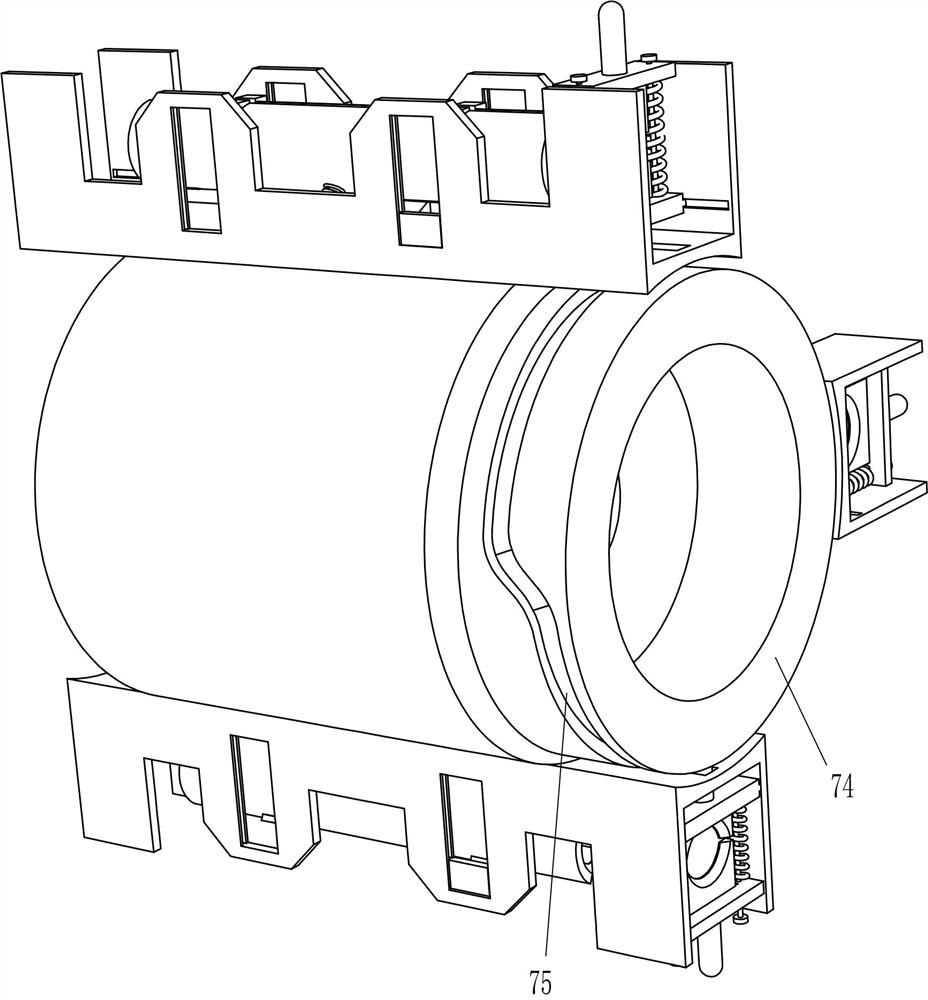
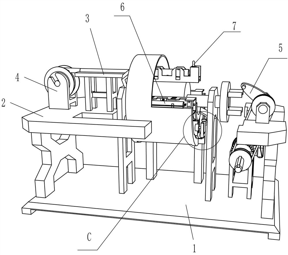
[0032] A device for stripping wire ends at both ends of an electric wire, such as figure 1 , figure 2 , image 3 , Figure 4 , Figure 5 , Image 6 with Figure 11 As shown, it includes a base 1, a workbench 2, a feeding table 3, a material rack 4, a rotating device 5, a clamping device 6 and a wire stripping device 7. The workbench 2 is fixed on the base 1, and the top left of the workbench 2 The feeding platform 3 is fixedly connected to the side, and the material rack 4 is fixedly connected to the left side of the top of the working table 2. The material rack 4 is located on the left side of the feeding table 3. A clamping device 6 is provided, and a stripping device 7 is provided between the rotating device 5 and the clamping device 6 .

[0033]The rotating device 5 includes a bracket 51, a motor 52, a first rotating shaft 53, a first vertical block 54, a second rotating shaft 55, a first transmission assembly 56, a first cam 57, a shift lever 58, a vertical plate 5...

Embodiment 2

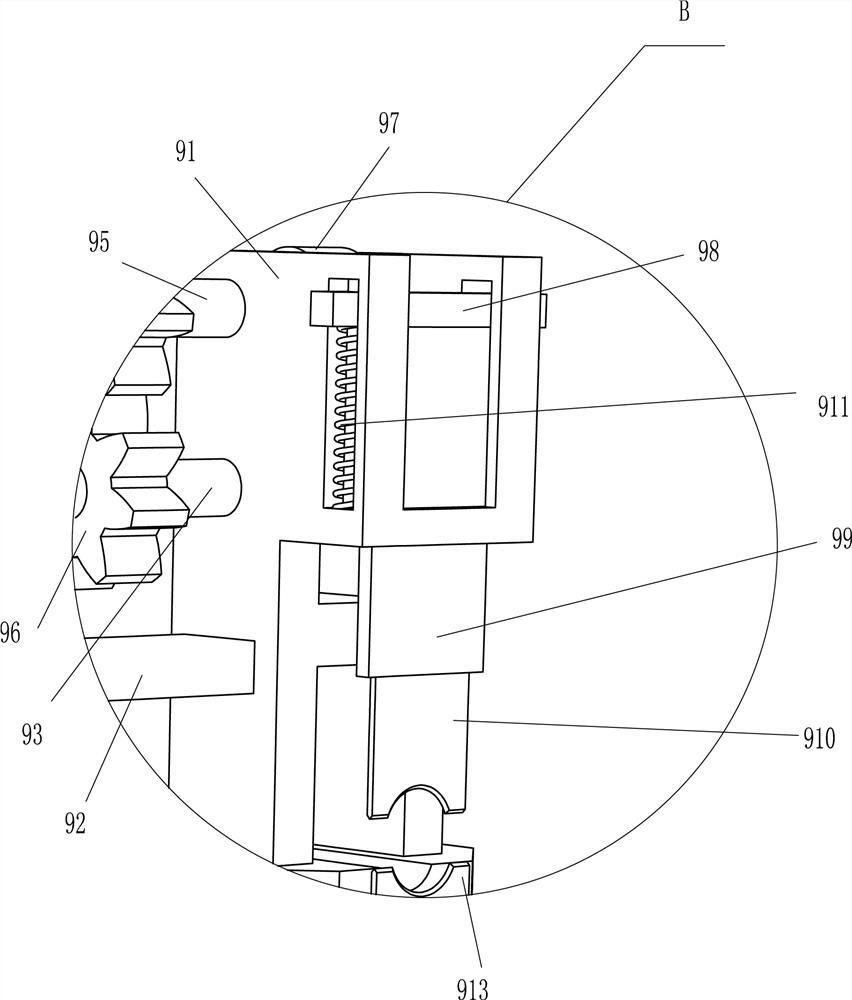
[0041] On the basis of Example 1, such as figure 1 , Figure 7 , Figure 8 with Figure 9 As shown, a driving device 8 is also included, and the driving device 8 includes a first H-shaped frame 81, a fourth rotating shaft 82, a second transmission assembly 83, a missing gear 84, a second H-shaped frame 85, a fifth rotating shaft 86, a One full gear 87, the second vertical block 88, the sixth rotating shaft 89, the third transmission assembly 810, the feeding column 811, the third vertical block 812, the seventh rotating shaft 813 and the fourth transmission assembly 814, the left front part of the top of the base 1 A first H-shaped frame 81 is fixedly connected, and the upper part of the first H-shaped frame 81 is rotatably provided with a fourth rotating shaft 82 , and a second transmission assembly 83 is connected between the middle circumferential direction of the fourth rotating shaft 82 and the front circumferential direction of the first rotating shaft 53 , The second...

Embodiment 3

[0046] On the basis of embodiment 1 and embodiment 2, such as figure 1 , figure 2 with Figure 10 As shown, it also includes a third H-shaped frame 10, a buffer spring 11 and a discharge hopper 12. The middle of the top of the base 1 is symmetrically provided with a third H-shaped frame 10, and both ends of the top of the third H-shaped frame 10 are fixedly connected with a buffer A discharge hopper 12 is affixed between the spring 11 and the tail ends of the four buffer springs 11 .

[0047] Also include special-shaped plate 13, contact cylinder 14 and sponge block 15, the bottom of fixed cylinder 72 left and right sides is all fixedly connected with special-shaped plate 13, and the top rear side of special-shaped plate 13 is rotated to be provided with contact cylinder 14, and the inner surface of special-shaped plate 13 A sponge block 15 is fixedly connected to the front side of the upper part.

[0048] When the peeling of the wire ends at the two ends of the electric w...


PUM


Abstract

The invention relates to a wire skin removing device and particularly relates to a wire skin removing device for two ends of a wire. The wire skin removing device for the two ends of the electric wirecan remove wire skins at the two ends of the electric wire at a time, and is high in working efficiency, convenient to operate and labor-saving. The wire skin removing device for the two ends of theelectric wire comprises a base, a feeding table and a material frame, wherein a workbench is installed on one side of the base; the feeding table is mounted on the workbench; and the material frame ismounted on the workbench. According to the device, the wire is sleeved on the material rack, a head end of the wire is pulled to move to a proper position in the material clamping device to be limited, the wire is cut off at the proper position by the scissors, the rotating device is started to drive the material clamping device to operate, the material clamping device operates to drive the wirestripping device to operate, and the wire stripping device operates to strip the two ends of the wire; and manual wire skin removal on two ends of the wire is not needed, so operation is convenient and labor-saving.

Description

technical field [0001] The invention relates to a wire sheathing device, in particular to a wire sheathing device at both ends of an electric wire. Background technique [0002] Electric wire refers to the wire that transmits electric energy. When people need to use the electric wire, both ends of the electric wire must be stripped. [0003] At present, most of the wires are manually peeled at both ends of the wire. First, people cut the wire to a suitable length, and then use a vise to cut off the wire at the end of the wire. This operation is laborious and both ends of the wire must be removed The wire sheath causes people to need to operate it twice, which is cumbersome, leads to low work efficiency, and easily leads to boredom in subsequent work. [0004] Therefore, there is a special need for a device that can remove the wire ends of the electric wire at one time, has high work efficiency, is also convenient to operate, and has a relatively labor-saving wire peeling de...

Claims


Application Information

Patent Timeline
Patent Type & Authority Applications(China)
IPC IPC(8): H02G1/12
CPCH02G1/1248H02G1/127H02G1/1265
Inventor 钟荣善
Owner 湖南诚合鑫科技有限公司
Why Eureka
Try Eureka