

Method of making applicator with precision eye opening
An eye, eye technology, applied in the field of preparing applicators with precise eye openings, can solve the problems of user discomfort, poor fit and registration, difficult alignment of eye openings and lip openings, etc.
- Summary
- Abstract
- Description
- Claims
- Application Information
AI Technical Summary
Problems solved by technology
Method used
Image

Examples
Embodiment 1
[0092] The eye opening 102 cutting path is digitally formed using methods according to the present disclosure. Figure 7A and Figure 7B A mask 100 formed from the developed custom eye opening 102 is shown.
[0093] Load the digital data corresponding to the 3D mesh of the face into the Blender graphics program. Align the face mesh flat with the nose pointing in the positive Z direction, the chin and forehead at roughly the same Z height, and the left and right cheeks at roughly the same Z height. Orients the face mesh to a top-down front view. The face mesh is viewed with and without the captured texture / color information to provide supplemental information on where the fiducials are located.
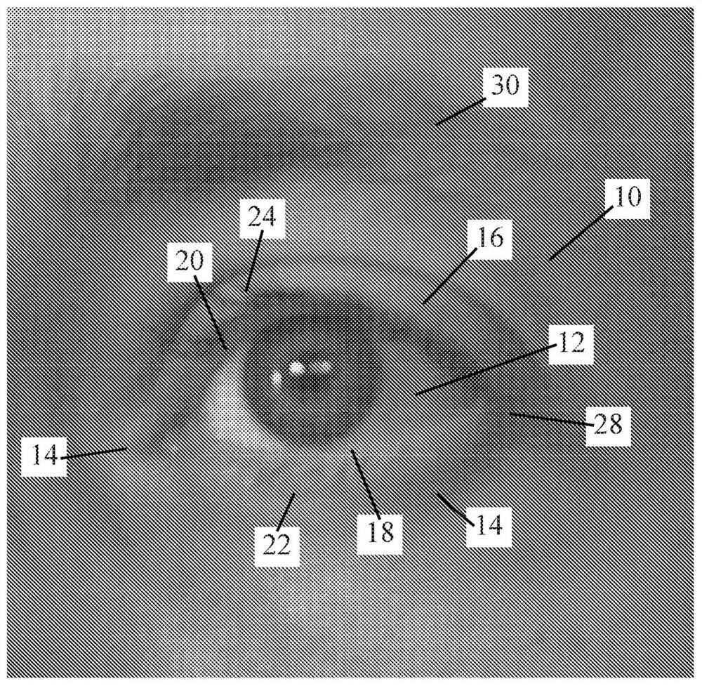
[0094] Select four anchor points on the digital geometric representation of the face rendered as a mesh. A lower eye region boundary 66 is defined at the minimum of the upper lashes 24 when the eye is closed. The first anchor point 104 is positioned about 3.5 mm below the lower bo...
Embodiment 2
[0098] Methods according to the present disclosure generate a facial mesh with eye openings 102 defined therein for direct printing of a mask with eye openings formed upon printing.
[0099] Load the digital data corresponding to the 3D mesh of the face into the Blender graphics program. Align the face mesh flat with the nose pointing in the positive Z direction, the chin and forehead at roughly the same Z height, and the left and right cheeks at roughly the same Z height. Orients the face mesh to a top-down front view. The face mesh is viewed with and without the captured texture / color information to provide supplemental information on where the fiducials are located.
[0100] Select four anchor points on the digital geometric representation of the face rendered as a mesh. A lower eye region boundary 66 is defined at the minimum of the upper lashes 24 when the eye is closed. The first anchor point 104 is positioned about 3.5 mm below the lower boundary 66 of the eye region...
Embodiment 3
[0104] The nose opening 114 cutting path is digitally formed using a method according to the present disclosure. Figure 12 Mask 100 formed from the developed custom nasal opening 114 is shown.
[0105] Load the digital data corresponding to the 3D mesh of the face into the Blender graphics program. Align the face mesh flat with the nose pointing in the positive Z direction, the chin and forehead at roughly the same Z height, and the left and right cheeks at roughly the same Z height. Orients the face mesh to a top-down front view. The face mesh is viewed with and without the captured texture / color information to provide supplemental information on where the fiducials are located.
[0106] Select four anchor points on the digital geometric representation of the face rendered as a mesh. The left anchor point 120 and the right anchor point 122 are set as midpoints of the outer nostril walls on either side 46 and 48 . The upper anchor point 118 is set at the center of the nos...
PUM
 Abstract
Description
Claims
Application Information