Casing wear ring automatic mounting device and method

A technology of automatic installation and mouth ring, which is applied in the direction of image data processing, instruments, computer parts, etc., can solve the problems of time-consuming, labor-intensive and low work efficiency

Active Publication Date: 2021-03-23
WUHU HIT ROBOT TECH RES INST
View PDF4 Cites 0 Cited by
  • Summary
  • Abstract
  • Description
  • Claims
  • Application Information

AI Technical Summary

Problems solved by technology

Most of the existing mouth rings are manually placed in the mouth ring base, which is time-consuming and labor-intensive, and the work efficiency is low

Method used


Image

  • Casing wear ring automatic mounting device and method
  • Casing wear ring automatic mounting device and method
  • Casing wear ring automatic mounting device and method

Examples


Embodiment Construction

[0063] The specific implementation of the present invention will be described in further detail below by describing the embodiments with reference to the accompanying drawings, so as to help those skilled in the art have a more complete, accurate and in-depth understanding of the inventive concepts and technical solutions of the present invention.

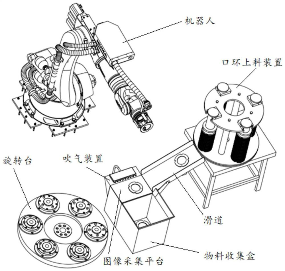
[0064] figure 1 The structural diagram of the automatic installation system for the mouth ring of the pump body provided by the embodiment of the present invention, for the convenience of description, only shows the parts related to the embodiment of the present invention.

[0065] The system also includes:

[0066] The mouth ring feeding device is connected with the image acquisition platform through the slideway;

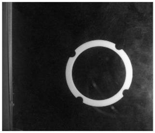
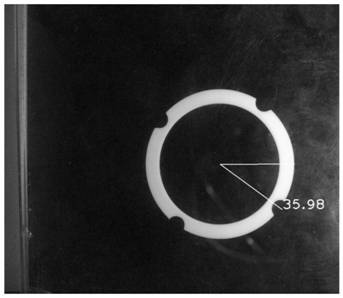
[0067] The industrial camera is used to collect the image of the mouth ring of the pump body on the image acquisition platform. The industrial camera is connected to the upper computer through communication. The upper...


PUM


Abstract

The invention discloses a casing wear ring automatic mounting device. The casing wear ring automatic mounting device comprises a wear ring feeding device, an industrial camera and a rotating table, wherein the wear ring feeding device is communicated with an image acquisition platform through a slideway, and is in communication connection with an electrical PLC server; the industrial camera is incommunication connection with an upper computer; a wear ring pose recognition device used for recognizing the casing wear ring pose is integrated on the upper computer; the rotating table is providedwith a circular rotating disc and a driving motor for controlling the circular rotating disc to rotate; a plurality of wear ring bases are uniformly arranged on the circular rotating disc; the drivingmotor controls the wear ring base to be assembled currently to rotate to a designated position; the driving motor is in communication connection with the electrical PLC server; and a robot client, the electrical PLC server and the upper computer are in communication connection. The pose data of a wear ring is obtained by identifying a wear ring image, the wear ring is adjusted to a placement teaching point pose according to the pose of the wear ring, and a convex point on the wear ring base is located in the concave arc of the wear ring when the wear ring is mounted on the wear ring base at the specified position, so that the wear ring is automatically and accurately mounted.

Description

technical field [0001] The invention belongs to the technical field of mouth ring installation, and more specifically, the invention relates to an automatic installation device and method for a pump body mouth ring. Background technique [0002] In the pump body manufacturing industry, the mouth ring is used as an installation component in the pump body. It needs to be placed in the mouth ring base with convex points. The correct posture of the placement is that the protrusions of the mouth ring base are inside the outer edge of the mouth ring A concave arc surrounds the area. Most of the existing mouth rings are manually placed in the mouth ring base, which has the problems of time-consuming and labor-intensive, and low work efficiency. Contents of the invention [0003] The invention provides an automatic installation device for the mouth ring of the pump body, aiming at improving the above problems. [0004] The present invention is achieved in this way, a pump body m...

Claims


Application Information

Patent Timeline
Patent Type & Authority Applications(China)
IPC IPC(8): B23P19/00B23P19/10G06K9/00G06K9/32G06K9/38G06K9/46G06T5/30
CPCB23P19/00B23P19/001B23P19/10G06T5/30G06V20/10G06V10/25G06V10/28G06V10/44
Inventor 于福才徐昌军邱羽张丹高云峰曹雏清樊璇韩硕
Owner WUHU HIT ROBOT TECH RES INST
Why Eureka
Try Eureka