English teaching book cutting trimming equipment
An English teaching and book technology, applied in metal processing and other directions, can solve the problems of low work efficiency and labor, and achieve the effect of high work efficiency and comprehensive scraps.
- Summary
- Abstract
- Description
- Claims
- Application Information
AI Technical Summary
Problems solved by technology
Method used
Image
Examples
Embodiment 1
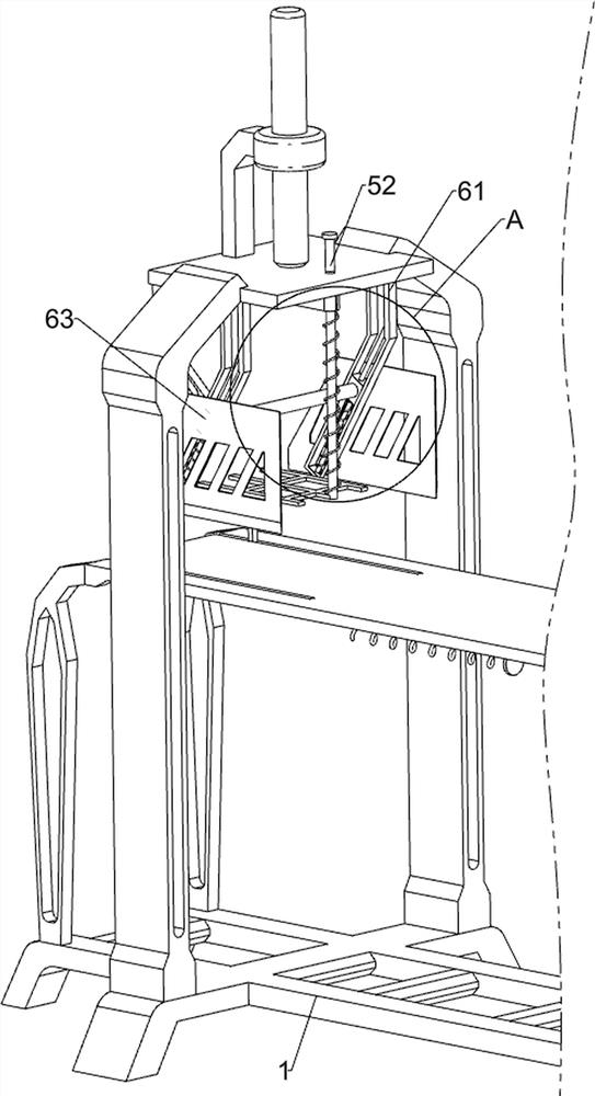
[0028] A kind of equipment for cutting and removing edges of English teaching books, such as Figure 1-Figure 3 As shown, it includes a base 1, a first support frame 2, a first cylinder 3, a second support frame 4, a pressing assembly 5 and a shear assembly 6, and the left side of the top of the base 1 is fixed with the first support frame 2, the second A first cylinder 3 is installed in the middle of the left side of the outer top of a support frame 2, and a compression assembly 5 is provided between the end of the telescopic rod of the first cylinder 3 and the first support frame 2, and a scissors are arranged on the top of the first support frame 2. Cutting assembly 6, the shearing assembly 6 cooperates with the pressing assembly 5, and the second support frame 4 is fixedly connected between the left and right sides of the top of the base 1.
[0029] The pressing assembly 5 includes a pressing rod 51, a first connecting rod 52, a pressing plate 53 and a first spring 54, and...
Embodiment 2
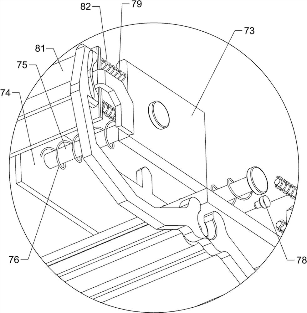
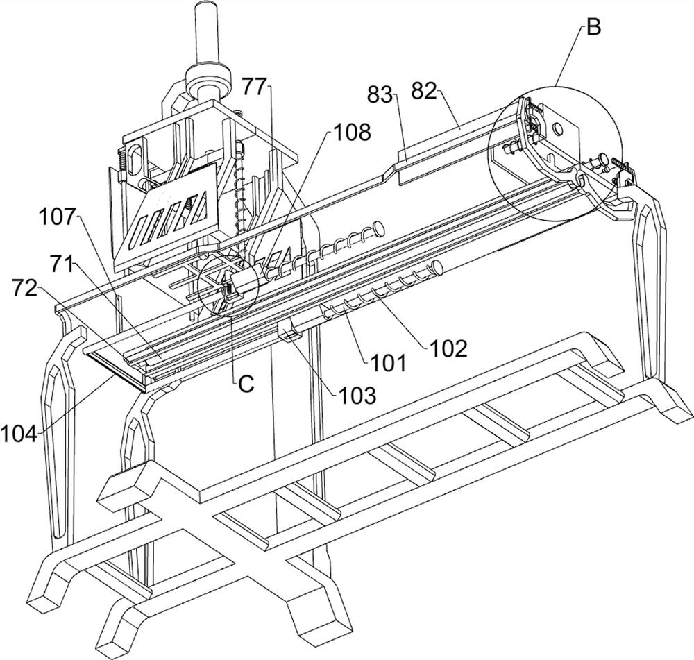
[0035] On the basis of Example 1, such as figure 1 , Figure 4 and Figure 5 Shown, also include pusher assembly 7, pusher assembly 7 includes second cylinder 71, push frame 72, connecting plate 73, pusher plate 74, second connecting rod 75, the 3rd spring 76, special-shaped retaining rod 77 , the start switch 78 and the fixed rod 79, the second cylinder 71 is affixed in the middle of the top of the second support frame 4, and the left end of the telescopic rod of the second cylinder 71 is affixed with a push frame 72, and the front and rear sides of the push frame 72 are fixed on the top. Two fixed rods 79 are connected, and a connecting plate 73 is fixedly connected between the inner ends of the four fixed rods 79. The front and rear parts of the connecting plate 73 are slidably connected with a second connecting rod 75, and the second connecting rods on the front and rear sides 75 left ends are fixedly connected with pusher plate 74, and the bottom of pusher plate 74 is i...
Embodiment 3
[0040] On the basis of embodiment 1 and embodiment 2, such as figure 1 , Figure 4 , Figure 6 , Figure 7 and Figure 8 As shown, a cutting assembly 9 is also included, and the cutting assembly 9 includes a guide rod 91, a second cutter 92, a fifth spring 93, a special-shaped limit slider 95, a sixth spring 96 and an L-shaped return rod 97 , the first support frame 2 is fixedly connected with guide rods 91 on the upper, front, and rear sides of the left side surface, and a second cutter 92 is slidingly arranged between the guide rods 91 on the front and rear sides, and the front and rear sides of the top of the second cutter 92 are connected to the The fifth spring 93 is wound around the top of the guide rod 91, and the embedded sliding type on the left side of the bottom of the pressure rod 51 is provided with a special-shaped limit slider 95, and there is a gap between the right side of the special-shaped limit slider 95 and the inside of the pressure rod 51. Connected ...
PUM
 Abstract
Description
Claims
Application Information
 - R&D
- Intellectual Property
- Life Sciences
- Materials
- Tech Scout
- Unparalleled Data Quality
- Higher Quality Content
- 60% Fewer Hallucinations
Browse by: Latest US Patents, China's latest patents, Technical Efficacy Thesaurus, Application Domain, Technology Topic, Popular Technical Reports.
© 2025 PatSnap. All rights reserved.Legal|Privacy policy|Modern Slavery Act Transparency Statement|Sitemap|About US| Contact US: help@patsnap.com


