Multifunctional filter for hydraulic system and assembly method of multifunctional filter

A hydraulic system and multi-functional technology, which is applied in the direction of fluid pressure actuation system components, fluid pressure actuation devices, fixing devices, etc., can solve the problem of inconvenient installation of the top cover or base of the filter, so as to increase the connection stability, The effect of reducing impact force and improving convenience

Active Publication Date: 2021-03-23
墨策智能技术(江苏)有限公司
View PDF10 Cites 0 Cited by
  • Summary
  • Abstract
  • Description
  • Claims
  • Application Information

AI Technical Summary

Problems solved by technology

[0005] In order to improve the problem of inconvenient installation of the top cover or base of the filter, the application provides a multifunctional filter for a hydraulic system and its assembly method

Method used


Image

  • Multifunctional filter for hydraulic system and assembly method of multifunctional filter
  • Multifunctional filter for hydraulic system and assembly method of multifunctional filter
  • Multifunctional filter for hydraulic system and assembly method of multifunctional filter

Examples


Embodiment 1

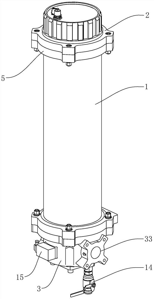
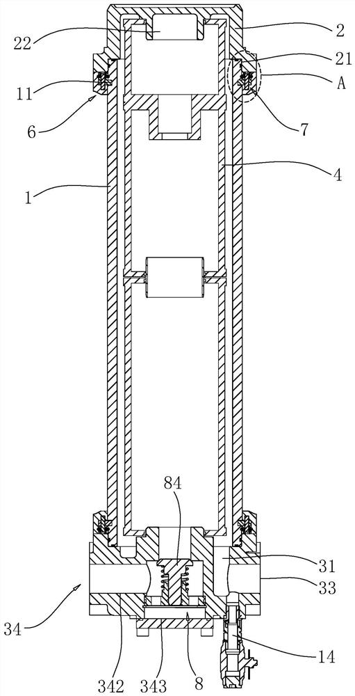
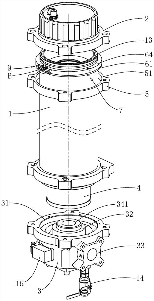
[0045] refer to figure 1 and figure 2 , the multifunctional filter includes a filter cartridge 1, a base 3, a top cover 2 and a filter element 4, and the filter cartridge 1 is provided with two connection seats 5 along the length direction, and the two connection seats 5 are away from each other and close to the filter cartridge 1 One side is provided with an annular fixing groove 51 . Both ends of the filter cartridge 1 along the length direction are provided with an annular groove 11 , and a stopper 6 is inserted into each of the two annular grooves 11 .

[0046] refer to figure 2 and image 3 , the limiting member 6 includes a semicircular limiting plate 61 inserted into the ring groove 11, and two limiting plates 61 are provided along the circumferential direction of the filter cartridge 1, and the end faces of the two limiting plates 61 are in conflict . The limit plate 61 is provided with an integrally formed fixed block 64 on the side away from the bottom wall o...

Embodiment 2

[0066] refer to Figure 8 The difference between this embodiment and Embodiment 1 is that the limiting member 6 includes a limiting ring 62 , and a fixing block 64 is provided on the inner wall of the limiting ring 62 . Both ends of the filter cartridge 1 along the length direction are provided with a pair of limiting grooves 12 , and the same pair of limiting grooves 12 are arranged along the circumferential direction of the filter cartridge 1 . The limiting groove 12 includes a vertical groove 121 provided on the end face of the filter cartridge 1 and an arc groove 122 communicating with the vertical groove 121. The vertical groove 121 is arranged along the axial direction of the filter cartridge 1, and the arc groove 122 is arranged along the axis of the filter cartridge 1. Arc direction setting.

[0067] refer to Figure 8 In the process of installing the limit ring 62, the operator aligns the limit block 63 with the notch of the vertical groove 121, and pushes the limit...


PUM


Abstract

The invention relates to a multifunctional filter for a hydraulic system and an assembly method of the multifunctional filter, which are applied to the technical field of hydraulic oil filters. The multifunctional filter comprises a filter cartridge, a top cover and a base, wherein the top cover and the base are arranged on the filter cartridge; the filter cartridge is sleeved with two connectingseats in the length direction; one connecting seat is used for fixing the top cover; the other connecting seat is used for fixing the base; and limiting pieces used for fixing the connecting seats arearranged on the filter cartridge. According to the multifunctional filter, the movement of the connecting seats in the axis direction of the filter cartridge is limited through the limiting pieces, so that the effect of fixing the top cover or the base is achieved, an operator can conveniently and rapidly install the top cover or the base, and the convenience of filter assembly is improved.

Description

technical field [0001] The present application relates to the technical field of hydraulic oil filters, in particular to a multifunctional filter for a hydraulic system and an assembly method thereof. Background technique [0002] The quality of hydraulic oil has a great influence on the working performance of the hydraulic system. Many failures are rooted in it. To prevent oil pollution, install hydraulic oil filters in appropriate places, which can trap pollutants in the oil and keep the oil clean. , to ensure the normal operation of the oil system. [0003] refer to Figure 9 , the filter in the related art includes a filter cartridge 1 and a top cover 2 at one end of the filter cartridge 1 and a base 3 at the other end. The side wall of the filter cartridge 1 is communicated with an oil inlet 33, and the base 3 is provided with the filter cartridge. 1 communicated with the oil outlet 34, the filter cartridge 1 is provided with a filter element 4 between the top cover 2 ...

Claims


Application Information

Patent Timeline
Patent Type & Authority Applications(China)
IPC IPC(8): F15B21/041F15B21/00F16B1/02F16L55/045
CPCF15B21/00F15B21/041F16B1/02F16L55/045
Inventor 邓玉林李余吴爱青吴开怀
Owner 墨策智能技术(江苏)有限公司
Why Eureka
Try Eureka