
Synchronization system and vehicle with same

A technology of synchronous system and synchronous hub, which is applied in the field of vehicles, can solve the problem of insufficient compact structure of the synchronous system, and achieve the effect of compact structure, reliable shifting performance, and compact overall structure

Active Publication Date: 2021-03-23
BYD CO LTD
View PDF22 Cites 2 Cited by
  • Summary
  • Abstract
  • Description
  • Claims
  • Application Information

AI Technical Summary

Problems solved by technology

[0002] In vehicles in the related art, the synchronizer usually realizes the synchronization function through the slider, and the locking function of the synchronizer needs to be realized by adding a limit steel ball on the shift fork lever that promotes the movement of the gear sleeve. The increase of the limit steel ball Will lead to the structure of the entire synchronization system is not compact enough

Method used


Image

  • Synchronization system and vehicle with same
  • Synchronization system and vehicle with same
  • Synchronization system and vehicle with same

Examples


Embodiment Construction

[0048] Embodiments of the present invention are described in detail below, examples of which are shown in the drawings, wherein the same or similar reference numerals designate the same or similar elements or elements having the same or similar functions throughout. The embodiments described below by referring to the figures are exemplary only for explaining the present invention and should not be construed as limiting the present invention.

[0049] In the description of the present invention, it should be understood that the orientations or positional relationships indicated by the terms "inner", "outer", "axial", "radial", and "circumferential" are based on the orientations shown in the drawings Or positional relationship is only for the convenience of describing the present invention and simplifying the description, but does not indicate or imply that the device or element referred to must have a specific orientation, be constructed and operated in a specific orientation, a...


PUM


Abstract

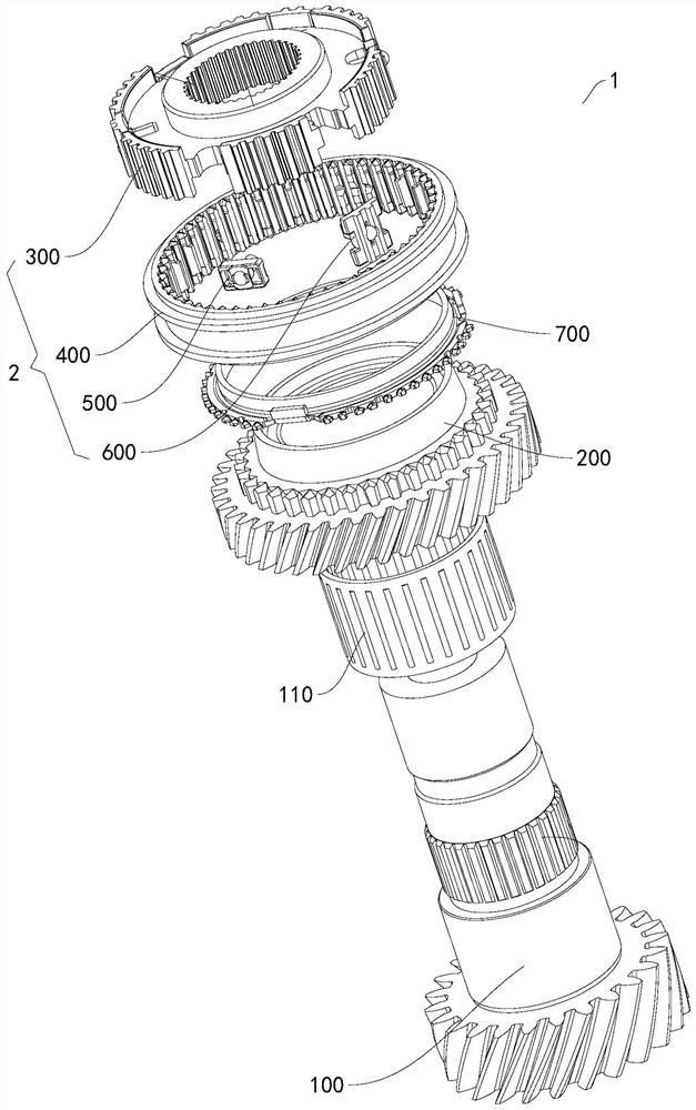
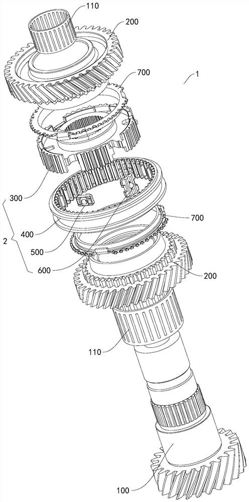
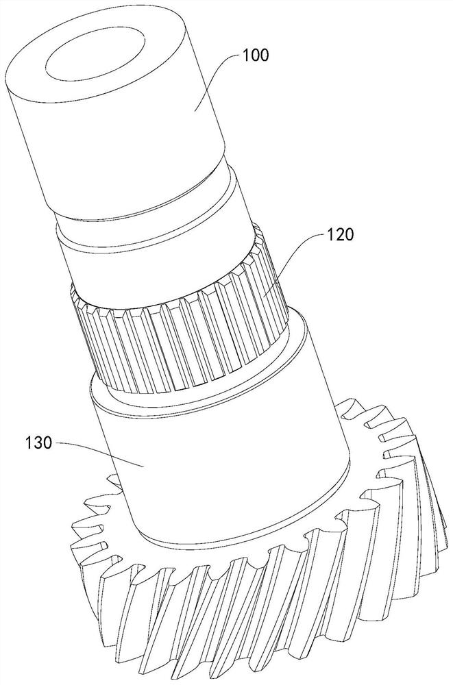
The invention discloses a synchronization system and a vehicle with the synchronization system. The synchronization system comprises a transmission shaft, a shifting gear, asynchronous hub, a gear sleeve, a synchronous sliding block, a locking and stopping block and asynchronous ring, wherein the shifting gear is arranged on the transmission shaft in a sleeving manner; the synchronous hub is arranged on the transmission shaft in a sleeving manner; the gear sleeve is arranged on the synchronous hub in a sleeving mode and can move between a neutral gear position and an in-gear position; the synchronous sliding block is arranged on the synchronous hub; the locking and stopping block is arranged on the synchronous hub, and when the gear sleeve is located at the in-gear position, the gear sleeve is stopped by the locking and stopping block so as to stop the gear sleeve from moving to the neutral position; the synchronous ring is arranged in a sleeving manner; when the gear sleeve is locatedat the neutral position, the gear sleeve is meshed with the synchronous hub and is separated from the shifting gear; when the gear sleeve moves from the neutral position to the in-gear position, thegear sleeve pushes the synchronous ring to make contact with the shifting gear through the synchronous sliding block; and when the gear sleeve is located at the in-gear position, the gear sleeve is meshed with the synchronous hub, the synchronous ring and the shifting gear. According to the synchronization system disclosed by the embodiment of the invention, the functions of synchronization, gearlocking and centering can be achieved, and the structure is compact.

Description

technical field [0001] The invention relates to the technical field of vehicles, in particular to a synchronization system and a vehicle with the synchronization system. Background technique [0002] In vehicles in the related art, the synchronizer usually realizes the synchronization function through the slider, and the locking function of the synchronizer needs to be realized by adding a limit steel ball on the shift fork lever that promotes the movement of the gear sleeve. The increase of the limit steel ball The structure of the entire synchronization system will not be compact enough. Contents of the invention [0003] The present invention aims to solve at least one of the technical problems existing in the prior art. For this reason, an object of the present invention is to propose a synchronization system which not only realizes the functions of synchronization and locking, but also has a compact structure. [0004] The invention also proposes a vehicle with the ...

Claims


Application Information

Patent Timeline
Patent Type & Authority Applications(China)
IPC IPC(8): F16D23/04F16D23/06
CPCF16D23/04F16D23/06F16D2023/0625F16D2023/0631F16D2023/0618
Inventor 阮飞
Owner BYD CO LTD
Learn More