Surgical medical instrument cleaning, drying and disinfecting device

A medical device and disinfection device technology, applied in the field of medical devices, can solve the problems of medical devices scratching the human body, damage of medical devices, waste of time, etc., and achieve the effect of convenient taking and putting, saving working time and cleaning clean

Inactive Publication Date: 2021-03-23
杨 志明
10 Cites 0 Cited by

AI-Extracted Technical Summary

Problems solved by technology

[0002] Many more serious diseases in surgery require surgery. During the surgical operation, some medical instruments are usually used. After the operation is completed, the medical staff need to clean the medical instruments. After cleaning, the medical instruments need to be dried, and then the medical Disinfection of instrument...

Method used

Please refer to 1 and Fig. 10, the air outlet end of exhaust pipe 19 is arranged on the right side wall of casing 1, is also provided with sound and light alarm 22 on the right side wall of casing 1, sound and light alarm 22 is arranged near the air outlet of the exhaust pipe 19, and the sound and light alarm 22 is electrically connected with the output end of the intelligent temperature controller. When the intelligent temperature controller controls the blower fan 15 and the electric heating wire 12 to start, it controls the sound and light alarm 22 to start simultaneously, reminding the medical staff to stay away from the air outlet end of the exhaust pipe 19, so as to avoid being burned by hot wind.
Please refer to 1 and Fig. 6, the electric heating box 14 is provided with a dispersion partition 16, the dispersion partition 16 is located between the air inlet of the electric heating wire 12 and the electric heating box 14, and the dispersion partition 16 is covered with air-permeable Through holes: the wind blown into the electric heating box 14 by the blower fan 15 is dispersed through the ventilation through holes on the dispersing partition 16 and evenly blows through each part of the electric heating wire 12, so that the electric heating wire 12 can be more effectively used after being energized. generated heat.
Please refer to 5, the middle part of the first horizontal dividing plate 5 is provided with a cylindrical through hole, the piston rod of the electric cylinder 10 passes in this cylindrical through hole, the cylindrical through hole of the first horizontal dividing plate 5 At least two annular grooves are arranged on the hole wall, and each annular groove is arranged sequentially along the height direction of the cylindrical through hole, and a sealing ring 13 is arranged in the annular groove, and the sealing ring 13 is pressed by the piston rod of the electric cylinder 10 tight. The sealing ring 13 forms a seal with the piston rod of the electric cylinder 10 and the hole wall of the cylindrical through hole of the first horizontal partition 5 to prevent water leakage.
Please refer to Fig. 1 and Fig. 5, also vertically be provided with electric cylinder 10 in the lower cavity of casing 1, the upper end of electric cylinder 10 piston rods upwards passes first horizontal dividing plate 5 and is positioned at casing 1 In the cavity, a grid plate 11 is horizontally arranged in the upper cavity of the box body 1 , and the upper end of the piston rod of the electric cylinder 10 is connected with the lower end surface of the grid plate 11 . The medical instruments are placed on the grid plate 11 for cleaning without contact with the first horizontal partition 5, so that the impurities falling off the medical instruments during the cleaning process will not repeatedly stick to the medical instruments, and the grid can be driven by the electric cylinder 10 The plate 11 ...

Abstract

The invention discloses a surgical medical instrument cleaning, drying and disinfecting device. The device comprises a cuboid box and further comprises a first vertical partition plate, second vertical partition plates, a first horizontal partition plate and a hot air supply device. An inner cavity of the box body is divided into a front cavity and a rear cavity by the first vertical partition plate, the two second vertical partition plates divide a front cavity of the box body into a left cavity body, a middle cavity body and a right cavity body, the middle cavity of the box body is divided into an upper cavity and a lower cavity by the first horizontal partition plate, an ultrasonic generator is arranged in the lower cavity, a plurality of vibration pieces are arranged on the upper end face of the first horizontal partition plate, the vibration pieces are connected to an energy converter, and the energy converter is electrically connected to the ultrasonic generator. The hot air supply device is used for supplying hot air into the upper cavity of the box body and carrying out hot air drying on cleaned and disinfected medical instruments in the upper cavity. According to the device, medical instruments can be cleaned, dried and disinfected in a centralized mode, and the medical instrument cleaning, drying and disinfecting efficiency is improved.

Application Domain

Technology Topic

Image

  • Surgical medical instrument cleaning, drying and disinfecting device
  • Surgical medical instrument cleaning, drying and disinfecting device
  • Surgical medical instrument cleaning, drying and disinfecting device

Examples

  • Experimental program(1)

Example Embodiment

[0035] In order to make the objects, technical solutions, and advantages of the present invention more clearly, the technical solutions in the embodiments of the present invention will be described in contemplation in the drawings of the embodiments of the present invention, and the embodiments described in the embodiments of the present invention will become apparent. It is a part of the embodiments of the invention, not all of the embodiments. Thus, the following detailed description of the embodiments of the invention as provided in the drawings are not intended to limit the scope of the invention as claimed, but only the selected embodiments of the present invention are shown. Based on the embodiments in the present invention, those of ordinary skill in the art will belong to the scope of the present invention without all other embodiments obtained without creative labor.
[0036] In the present invention, the terms "installation", "connected", "connection", "fixed", such as the term "mount", "connected", "linked", "fixed", unless otherwise expressly specifically understood, for example, can be a fixed connection, or a detachable connection One integration; may be mechanical connection, or electrical connection; may be directly connected, or indirectly connected by an intermediate medium, which may be a communication between two elements or two components. Relationship. For those skilled in the art, the specific meaning of the above terms can be understood in terms of specific cases.
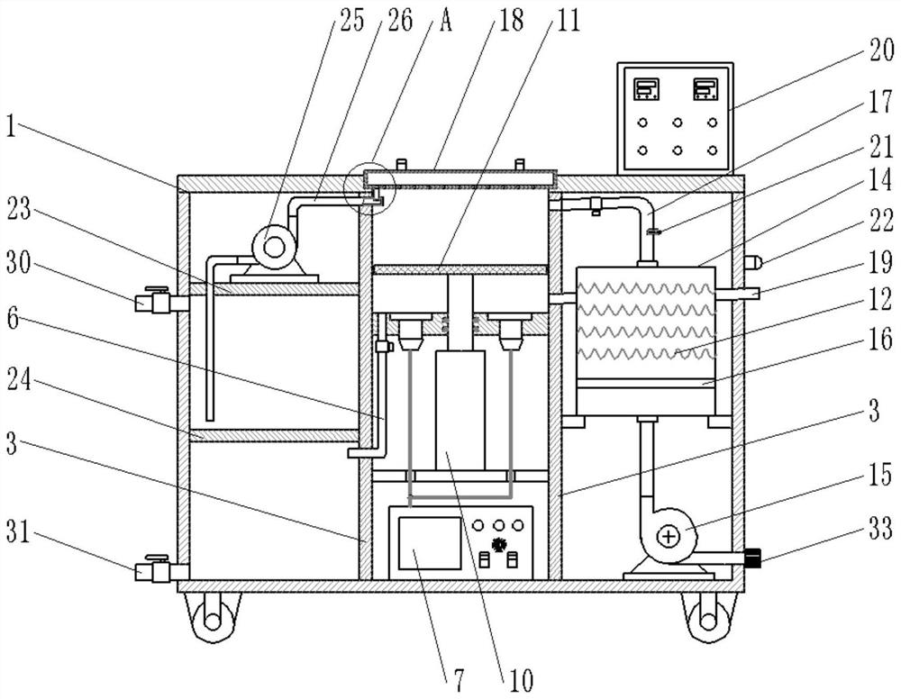
[0037] Surgical medical equipment cleaning and drying disinfection device, please refer to figure 1 , Figure 4 with Figure 5 , Including the rectangular shaped casing 1, further comprising the first vertical separator 2, the second vertical separator 3, the first horizontal separator 5, and the hot air supply device; the first vertical separator 2 is disposed vertically in the box In the body 1, and its length direction is disposed in the longitudinal direction of the casing 1, the first vertical separator 2 separates the inner cavity of the casing 1 into a front cavity and a rear cavity. The second vertical separator 3 is provided with two, and all vertically disposed in the front cavity of the casing 1, and its length direction is disposed in the width direction of the casing 1, two second vertical separator 3 The front cavity of the box 1 is separated into a left cavity, a middle cavity, and a right cavity.
[0038] The first horizontal separator 5 is horizontally disposed in the casing 1 in the case, separated by the middle cavity of the casing 1 into the upper cavity and the lower cavity, the upper body and the lower cavity are not in communication, the upper body The upper end opening is provided, and the upper portion of the box 1 upper cavity is provided with a step structure, and the box cover 18 is placed in this step structure, and the first horizontal separator 5 is provided with a drain pipe 6, and the drain valve is provided on the drain pipe 6. The lower chamber is provided with an ultrasonic generator 7, and a plurality of vibrating sheets 8 are provided on the upper end surface of the first horizontal separator 5, and the vibrating sheet 8 is connected to the transducer 9, the transducer 9 and the ultrasonic generator 7 Sexual connection. Ultrasonic generator 7, the vibrating sheet 8 and the transducer 9 form an ultrasonic cleaning device. The hot air supply device is used to supply hot air to the upper cavity of the casing 1, and the hot air drying is carried out in the upper cavity.
[0039] The working principle of the present invention: places the use of the medical device in the case of the case 1, add disinfection and cleaning water to the casing 1, disinfecting the water without a medical device, activates the ultrasonic cleaning device, on the cabinet 1 The medical device in the cavity is ultrasonic cleaning, after the cleaning is completed, the drainage valve is opened, and the disinfectant cleaning water used in the box 1 is discharged through the drain pipe 6. The hot air supply device is thermally drying the medical device in the upper cavity of the casing 1 after the disinfecting cleaning water in the upper cavity is emptied. Therefore, the present invention can be concentrated, dried, and disinfect in the medical device, improve the efficiency of cleaning, drying, and disinfection of medical instruments, saving the working hours of medical staff.
[0040] See figure 1 with Figure 5 The electric cylinder 10 is also provided in the lower chamber of the box 1, and the upper end of the electric cylinder 10 piston rod is located in the upper cavity of the case 1, the upper cavity of the casing 1. In the body, a mesh plate 11 is provided, and the upper end of the electric cylinder 10 piston rod is connected to the lower end surface of the mesh plate 11. The medical device is placed on the grid plate 11, not in contact with the first horizontal separator 5, so that the impurities that fall off during the cleaning process do not repeat the medical device, and can be driven by the electric cylinder 10 The board 11 and the medical device are moved up and down, one is to facilitate the fall of impurities on the medical device, and the other is more convenient to take and put in medical devices from the upper body.
[0041] Referring to 5, the middle portion of the first horizontal separator 5 is provided with a cylindrical through hole, and the piston rod of the electric cylinder 10 is thus passed through the cylindrical through hole, the first horizontal separator 5 is formed on the hole wall of the cylindrical vias At least two annular grooves are provided, each annular groove is sequentially disposed along the height direction of the cylindrical vias, and a sealing ring 13 is provided in the annular groove, and the sealing ring 13 is pressed against the piston rod of the electric cylinder 10. The seal ring 13 is sealed between the piston rod of the electric cylinder 10 and the hole wall of the cylindrical vias of the first horizontal separator 5 to prevent leakage.
[0042] Please refer to 1, the hot air supply device includes an electric heating tank 14 and a fan 15, and the electric heating box 14 and the fan 15 are disposed in the right cavity of the box 1, and the electric heating box 14 is provided with an air outlet and an outlet, electric heating. The inner portion of the box 14 is provided with an electric heating wire 12, and the electric heating wire 12 is disposed between the vent and the air outlet of the electric heating tank 14, and the air opening of the electric heating tank 14 is connected to the fan 15, and the air opening of the electric heating box 14 is connected. There is a ventilation end of the air supply pipe 17, the air supply pipe 17 is connected to the upper cavity of the box 1, and the air supply roller 17 is provided, and the cavity wall of the cavity of the chamber of the casing 1 is connected. Drainage 19, exhaust valve 19 is provided on the exhaust pipe 19.
[0043] When cleaning the medical device, the air supply valve and the exhaust valve are closed, and the medical device needs to be dried, and the wind generated by the fan 15 is heated after the electric heating box 14 is heated to enter the upper cavity of the casing 1. The medical device for cleaning and disinfecting in the upper cavity of the box is rapidly dry, and the drying efficiency is improved, and the drying time is lowered.
[0044] See 1 and Figure 6 The dispersion separator 16 is provided in the electric heating box 14, and the dispersion separator 16 is located between the electric heating wire 12 and the air opening of the electric heating tank 14, and the dispersion separator 16 is spread throughout the air; blowing electricity by the fan 15 The wind in the heating box 14 is uniformly blown over the exhaust through-hole dispersion on the discrete passage 16, and the heat generated by the electric heating wire 12 is electrically generated by electrically adding heat.
[0045] The suction port of the fan 15 is connected to the suction pipe, and the air supply end of the suction pipe is located outside the casing 1, and this end thread is mounted with a filter network tube 33, and the filter network pipe 33 is provided with a filter 34, so that the fan 15 can be prevented from preventing the fan 15 The dust in the outer air is blown into the upper cavity of the casing 1, the medical device is contaminated; the outer wall of the filtration network pipe 33 is provided on the outer wall of the network pipe 33, which is easy to remove the removal replacement of the filter network pipe 33.
[0046] See 1 and Figure 10 In addition, the present invention further includes a power control box 20, a power sensor 21, a temperature sensor 21, a temperature sensor 21, a temperature sensor 21, a temperature sensor 21, a temperature sensor 21, a temperature sensor 21, a temperature sensor 21, and a thermos 10 The input of the controller is connected, and the fan 15 and the electric heating wire 12 are electrically connected to the output of the smart thermostat.
[0047] The temperature sensor 21 can detect the temperature of the hot air, a hot air warning temperature value is provided on the intelligent thermostat, and when the temperature detected by the temperature sensor 21 reaches the hot air warning temperature value, the intelligent temperature controller controls the electric heating wire 12 to stop heating, prevent hot air The temperature is too high to damage the medical device. When the temperature detected by the temperature sensor 21 is lower than the hot air warning temperature value, the intelligent thermostat controls the electric heating wire 12 to continue to heat, preventing the hot air temperature from being too low, and the drying speed is too slow, guaranteed Dry efficiency.
[0048] See 1 and Figure 10 The outlet of the exhaust pipe 19 is disposed on the right side wall of the casing 1, and there is a sound alarm 22 on the right side wall of the casing 1, and the sound light alarm 22 is close to the wind exhaust pipe 19. The end setting, the sound and light alarm 22 is connected to the output of the smart thermostat. When the intelligent temperature controller control fan 15 and the electric heating wire 12 are activated, while controlling the sound and light alarm 22 to start, reminding medical staff away from the outlet of the exhaust pipe 19 to avoid being burned by hot air.
[0049] Referring to 1, the supply rustling pipe 17 is inclined with a tubular body coupled to the cavity wall of the chamber of the casing 1, and this tube body is connected to one end of the cavity wall of the chamber of the casing 1. And the air supply valve is disposed on this tube body; the exhaust pipe 19 is tilted, and one end connecting one end connected to the cavity wall of the casing 1 is low.
[0050] When drained by the drain pipe 6, the air supply pipe 17 and the venting pipe 19 entering the air intake into the upper cavity of the casing 1, and then drained by the drain pipe 6, the drying is not adversely affected.
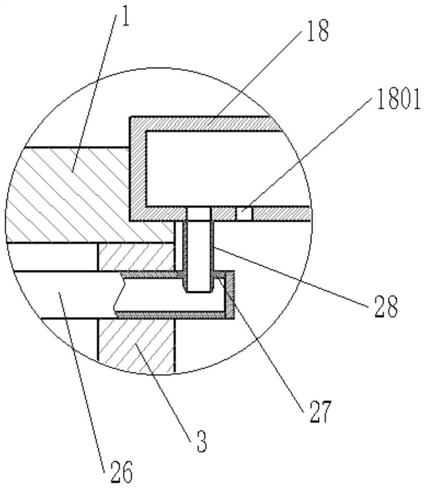
[0051] See figure 1 , figure 2 , Figure 7 , Figure 8 with Figure 9 The second horizontal separator 23 and the third horizontal separator 24, the second horizontal separator 23 and the third horizontal separator 24 are provided in the left cavity of the casing 1, and the left cavity of the casing 1 is downward. Separated into a water pump mounting chamber, a water pump cavity, and a sewage chamber, a water pump mounting chamber is attached to the water pump 25, and the water pump 25 is connected to the water pump, the water pump is inserted into the bottom of the water pump, and the water pump 25 is connected to the water pump 25 The water pipe 26, the water supply end of the water pipe 26 passes through the second vertical separator 3 on the left side is located in the upper cavity of the box 1, and the water supply end sealing of the water pipe 26 is provided, and the water pipe 26 is located in the casing 1. A rubber sleeve 27 is provided on the upper end tube wall of the tube body in the body, and a rubber sleeve 27 is provided on the hole wall of the insertion through hole, and a cylindrical coupling through hole is provided on the rubber sleeve 27; the cover 18 is a hollow structure. The lower end wall of the cover 18 is disposed vertically with a tube 28 connected thereto.
[0052] When the cover 18 is placed in the step structure of the upper port of the upper cavity, the insertion tube 28 is inserted into the cylindrical coupling through hole provided on the rubber sleeve 27, and the cylindrical plug-in through hole is connected to the insertion tube 28, so that The insertion tube 28 is sealed between the rubber sleeve 27. A chamfer structure is provided on the lower end outer tube wall of the insert tube 28, facilitating the cylindrical coupling through hole of the rubber sleeve 27; the lower end wall of the cover 18 is provided with a plurality of waterproof holes 1801, the upper end of the cover 18 The wall is provided with a handle 29 for easy storage cover 18. A hydrating tube 30 is provided on the upper side wall of the water purification chamber, and a hydrating valve is provided on the hydrating pipe 30, and a clean disinfection and cleaning water can be added to the watery pipe 30 through the hydrating pipe 30. The sewage pipe 31 is provided on the lower end side wall of the sewage chamber, and a sewage valve is provided on the sewage tube 31; the sewage chamber is located on the lower side of the upper cavity of the box 1, and the lower end of the drain pipe 6 extends into the sewage chamber, the box 1 The disinfectant cleaning water used in the upper cavity is first discharged into the sewage chamber by the drain pipe 6, and then discharged through the sewage pipe 31.
[0053] The water pump 25 is activated, and the water pump 25 pumps the purification of the water in the clean water chamber to the water pipe 26, and then passes through the insertion tube 28 into the hollow structure of the box cover 18, and finally through the water hole 1801 through the lower end wall of the box 18 The lower spray, and the medical device after disinfection is cleaned, and the medical device cleans more clean.
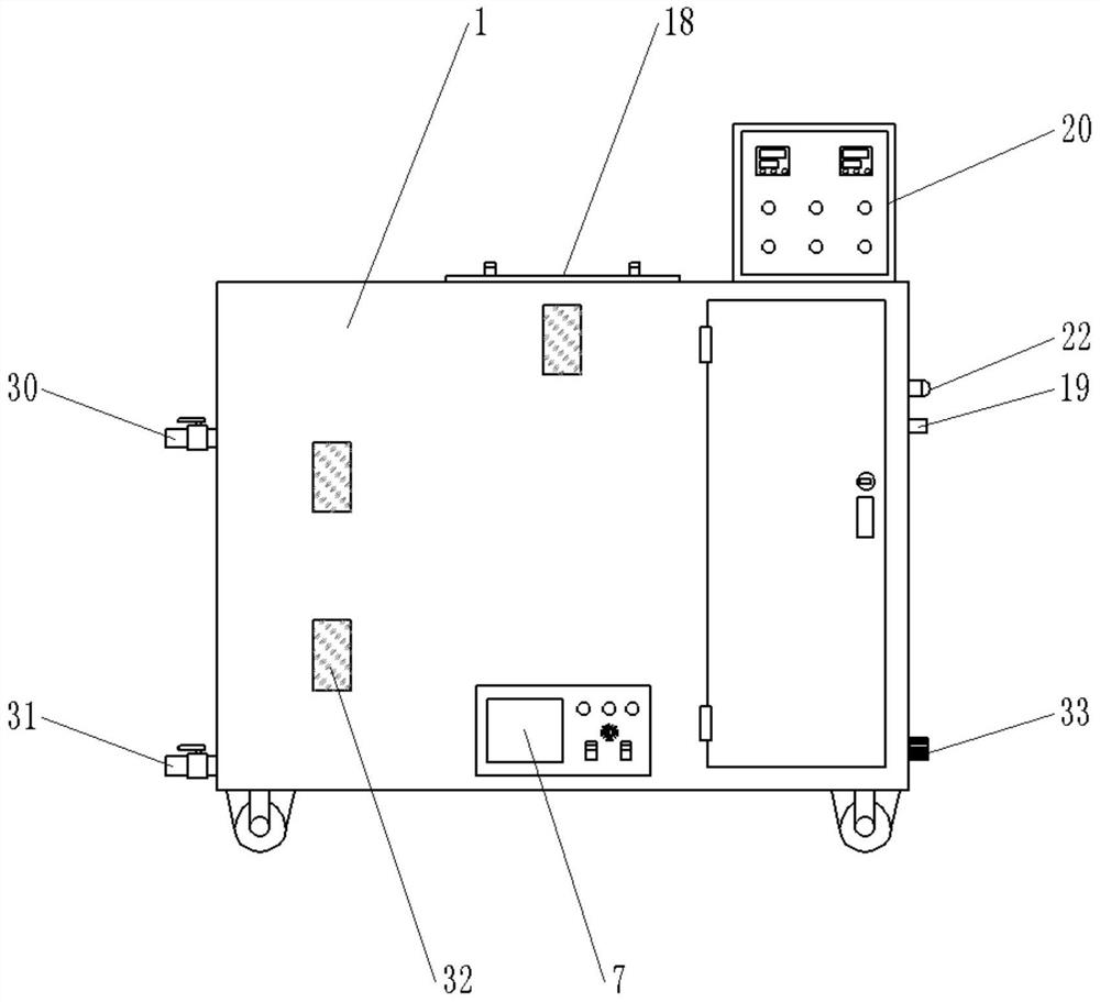
[0054] See image 3 The front side wall of the box 1 corresponds to the position of the chamber, the clean water chamber, and the sewage chamber of the casing 1, which is convenient for observing the cavity, water cavity of the casing 1. The water level of the sewage chamber, the bottom end of the casing 1 is provided with a wheel, which is convenient for the movement of the present invention.
[0055] The above is only preferred embodiments of the present invention, and is not intended to limit the invention, and the present invention can have various changes and variations for those skilled in the art. Any modification, equivalent replacement, improvement, etc. according to the spirit of the invention should be included within the scope of the invention.

PUM

no PUM

Description & Claims & Application Information

We can also present the details of the Description, Claims and Application information to help users get a comprehensive understanding of the technical details of the patent, such as background art, summary of invention, brief description of drawings, description of embodiments, and other original content. On the other hand, users can also determine the specific scope of protection of the technology through the list of claims; as well as understand the changes in the life cycle of the technology with the presentation of the patent timeline. Login to view more.

Similar technology patents

Collection workstation and method for collecting electronic evidence of site enforcement recorder

InactiveCN103294835ASave manpower and costSave time at workData acquisition and loggingEnforcementData information
Owner:SHENZHEN JINGYI DIGITAL TECH

Classification and recommendation of technical efficacy words

  • Save time at work
  • Easy to put in and take out

Control method of vehicle battery cooling system

InactiveCN103855440ASave time at workReduce battery power consumptionSecondary cellsPropulsion coolingElectrical batteryRefrigerant
Owner:SAIC MOTOR

Distillatory kettle for plant sesame oil

ActiveCN104606909ASimple structureEasy to put in and take outDistillation in boilers/stillsEssential-oils/perfumesWater tanksHeat energy
Owner:GUANGXI BONENG BIOMASS ENERGY TECH CO LTD

Fluorescence detection instrument and system based on micro-fluidic chip

InactiveCN105388131AGood light protectionEasy to put in and take outFluorescence/phosphorescenceMicro fluidicMicrofluidic chip
Owner:THE NAT CENT FOR NANOSCI & TECH NCNST OF CHINA

Rotary tower type non-stop unwinding equipment

ActiveCN111532846AImprove efficiencyEasy to put in and take outWebs handlingWall plateIndustrial engineering
Owner:青州蒙特机械有限公司
Why Eureka
Try Eureka