Self-locking compression type portable grounding wire capable of being disassembled and assembled quickly
What is AI technical title?
AI technical title is built by Patsnap AI team. It summarizes the technical point description of the patent document.
A compression type, self-locking technology, applied in the direction of clamping/spring connection, parts of connection device, connection, etc., can solve the problems of no continuous force, loss of safety measures, small locking force, etc. The effect of making force, fixing firm, and locking force
Pending Publication Date: 2021-03-23
国家能源泰安热电有限公司
View PDF0 Cites 0 Cited by
Summary
Abstract
Description
Claims
Application Information
AI Technical Summary
This helps you quickly interpret patents by identifying the three key elements:
Problems solved by technology
Method used
Benefits of technology
Problems solved by technology
[0003] The spiral compression portable grounding wire is the most common type of grounding wire. It consists of a wire end clamp, a short circuit wire, a grounding end clamp and an insulating rod; Rotate the jaws of the terminal clamp counterclockwise to open, buckle the copper bar that needs to be grounded, and then turn the insulation rod clockwise to lock the jaws. The force keeps it locked, and the friction force of the thread alone causes the locking force to be too small. A little movement or accidental contact will easily loosen the jaws, the clamp will fall off, and the operator will lose safety measures; therefore, for this In this case, a self-locking compression type portable ground wire that can be quickly disassembled is designed. This self-locking compression type portable ground wire that can be disassembled quickly through the cooperation of the card plate, the wedge-shaped groove and the spring, the locking force is strong. , the fixed is relatively firm, easy to disassemble, and can be better suitable for occasions where the operating space is relatively small, ensuring the safety of the operator
Method used
Image
Click on the blue label to locate the original text in one second.
Reading with bidirectional positioning of images and text.
Examples
Embodiment Construction
[0023] A self-locking compression type portable ground wire that can be quickly disassembled and assembled according to the present invention will be further described in detail below in conjunction with the accompanying drawings.
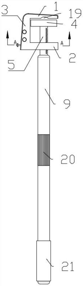
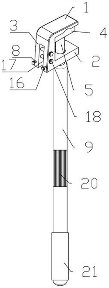
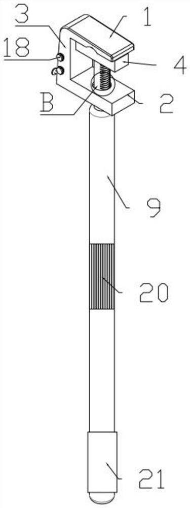
[0024] combined with Figure 1-6 , a self-locking compression type portable ground wire that can be quickly disassembled and assembled, including an upper splint 1, a lower splint 2, a vertical splint 3, a movable splint 4, a support rod 5, a fixed clip 6, a movable clip 7, and a round rod 8 and an insulating rod 9, one end of the upper splint 1 is connected to the upper end of the vertical splint 3, one end of the lower splint 2 is connected to the lower end of the vertical splint 3, one end of the support rod 5 is connected to one end of the insulating rod 9, The lower splint 2 is provided with a first round hole 10, the other end of the support rod 5 passes through the first round hole 10 and extends out of the first round hole 10, and the movab...
PUM
Abstract
The invention discloses a self-locking compression type portable grounding wire capable of being assembled and disassembled quickly, which comprises an upper clamping plate, a lower clamping plate, avertical clamping plate, a movable clamping plate, a supporting rod, a fixed clamping piece, a movable clamping piece, a round rod and an insulating rod, and is characterized in that one end of the upper clamping plate is connected with the upper end of the vertical clamping plate, one end of the lower clamping plate is connected with the lower end of the vertical clamping plate, one end of the supporting rod is connected with one end of the insulating rod, a first round hole is formed in the lower clamping plate, the other end of the supporting rod penetrates through the first round hole andextends out of the first round hole, the movable clamping plate is arranged at the end, which extends out of the first round hole, of the supporting rod, a wedge-shaped groove is formed in the supporting rod, a cavity is formed in the lower clamping plate, the fixed clamping piece is arranged on the side, which is close to the vertical clamping plate, in the cavity, the movable clamping piece is arranged on the side, which is away from the vertical clamping plate, in the cavity, a spring is arranged at the end, which is away from the vertical clamping plate, of the movable clamping piece, theother end of the spring is connected with the lower clamping plate, a clamping plate is arranged at the end, which is close to the vertical clamping plate, of the movable clamping piece and matched with the wedge-shaped groove.
Description
technical field [0001] The invention relates to the technical field of line detection equipment, in particular to a self-locking and compacting portable grounding wire that can be quickly disassembled and assembled. Background technique [0002] When power equipment needs power outage maintenance, in order to ensure the safety of operators, it is necessary to install temporary grounding wires on each possible incoming power side of the power outage maintenance equipment to ensure that operators are protected when there is residual charge, induced charge, or wrong power transmission. Personal safety, avoid electric shock, [0003] The spiral compression portable grounding wire is the most common type of grounding wire. It consists of a wire end clamp, a short circuit wire, a grounding end clamp and an insulating rod; Rotate the jaws of the terminal clamp counterclockwise to open, buckle the copper bar that needs to be grounded, and then turn the insulation rod clockwise to l...
Claims
Application Information
Patent Timeline
Application Date:The date an application was filed.
Publication Date:The date a patent or application was officially published.
First Publication Date:The earliest publication date of a patent with the same application number.
Issue Date:Publication date of the patent grant document.
PCT Entry Date:The Entry date of PCT National Phase.
Estimated Expiry Date:The statutory expiry date of a patent right according to the Patent Law, and it is the longest term of protection that the patent right can achieve without the termination of the patent right due to other reasons(Term extension factor has been taken into account ).
Invalid Date:Actual expiry date is based on effective date or publication date of legal transaction data of invalid patent.

