A drinking water device for animal husbandry

A technology for drinking water device and animal husbandry, applied in the field of animal husbandry, can solve the problems of inability to meet the needs of use, inability to achieve automatic water supply, inability to automatically supply water and stop water, etc.

Active Publication Date: 2022-04-19
诸城市中裕机电设备有限公司
View PDF0 Cites 0 Cited by
  • Summary
  • Abstract
  • Description
  • Claims
  • Application Information

AI Technical Summary

Problems solved by technology

[0003] The existing drinking water device for animal husbandry cannot automatically supply water when it is used, it needs to be operated manually, and it cannot automatically supply water and stop water according to the behavior of animals, which cannot meet the needs of use. Therefore, a drinking water device for animal husbandry is invented.

Method used


Image

  • A drinking water device for animal husbandry
  • A drinking water device for animal husbandry
  • A drinking water device for animal husbandry

Examples


Embodiment 1

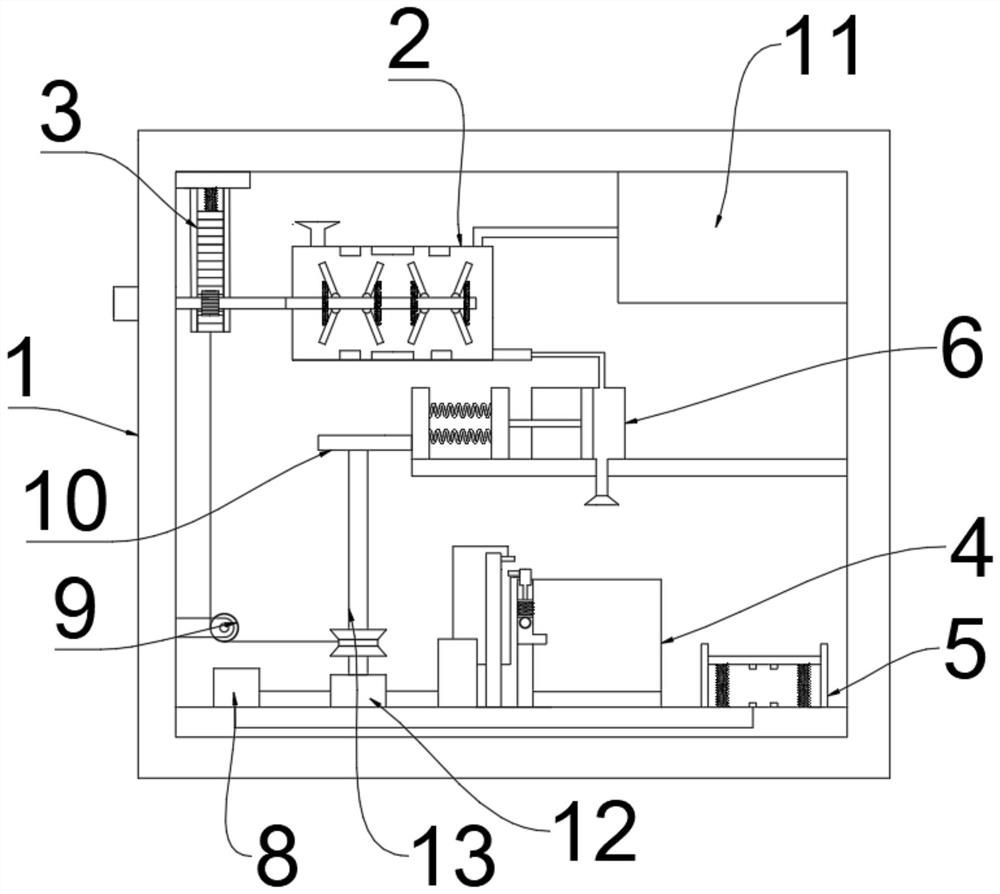
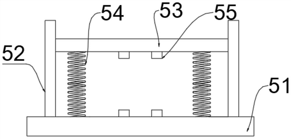
[0029] refer to Figure 1-5, a drinking water device for animal husbandry, comprising a fuselage 1 and a trigger device 5 arranged on the inner bottom surface of the fuselage 1, a drinking tank 4, an electric controller 8 and a motor 12, and a water storage device is installed on the inner wall of the fuselage 1 2 and the water supply device 6, and the water storage device 2 is connected to the water supply device 6 through a conduit, and the trigger device 5 includes a bottom plate 51 fixed on the inner bottom surface of the fuselage 1, and two side plates 52 are symmetrically installed above the bottom plate 51, and A pressure plate 53 is slidably connected between the two side plates 52, two telescopic springs 54 are connected between the pressure plate 53 and the bottom plate 51, two trigger blocks 55 are arranged on the opposite surfaces of the pressure plate 53 and the bottom plate 51, and the trigger blocks 55 pass through The wire is connected to the electric controlle...

Embodiment 2

[0034] refer to Image 6 , a drinking water device for animal husbandry. Compared with Embodiment 1 in this embodiment, the water storage device 2 includes a water supply tank 21 fixed on the inner wall of the fuselage 1, and the connecting shaft 36 is connected with a stirring tank arranged inside the water supply tank 21. shaft 22, and the side of the stirring shaft 22 is connected with several stirring devices 7, the stirring device 7 includes a first pressing rod 71 and a second pressing rod 72 symmetrically arranged on both sides of the stirring shaft 22, and the first pressing rod 71 and the second pressing rod The two pressure rods 72 are hinged with the stirring shaft 22, the third spring 73 is connected between the first pressure rod 71 and the second pressure rod 72, and several permanent magnets 23 are arranged on the inner walls of both sides of the water supply tank 21. Heater 24 is arranged on the both sides inner wall of 21, and water supply tank 21 is connected...


PUM


Abstract

The invention discloses a drinking water device for animal husbandry, which comprises a fuselage, a trigger device arranged on the inner bottom surface of the fuselage, a drinking tank, an electric controller and a motor, and a water storage device is installed on the inner wall of the fuselage and a water supply device, and the water storage device is connected to the water supply device through a conduit, and the trigger device includes a bottom plate fixed on the inner bottom surface of the fuselage, and two side plates are symmetrically installed above the bottom plate. When the present invention is used, it is convenient to trigger the water supply according to the animals by setting the trigger device, it is convenient to supply water in time according to the signal by setting the water supply device and the water storage device, and it is convenient for the water in the drinking tank to reach the appropriate level by setting the side hole, the soft ball and the breaker. When the animal is in the position, the power supply is cut off to stop the water supply. When the animal goes up to the pressing plate, the compressed telescopic spring moves down, and at the same time, the trigger blocks are brought into contact with each other.

Description

technical field [0001] The invention relates to the technical field of animal husbandry, in particular to a drinking water device for animal husbandry. Background technique [0002] In the early stages of economic development, animal husbandry often appears as a sideline of crop production, which is the so-called "backyard animal husbandry". With the development of the economy, it has gradually developed into a relatively independent industry in some sectors. For example: laying hen industry, broiler industry, dairy industry, beef cattle industry, pig industry, etc. [0003] The existing drinking water device for animal husbandry cannot automatically supply water when it is used, it needs to be operated manually, and it cannot automatically supply water and stop water according to the behavior of animals, which cannot meet the needs of use. Therefore, a drinking water device for animal husbandry is invented. . Contents of the invention [0004] The purpose of the presen...

Claims


Application Information

Patent Timeline
Patent Type & Authority Patents(China)
IPC IPC(8): A01K7/06A01K7/04A01K39/02A01K39/024B01F27/118B01F27/60B01F31/40B01F31/445B01F33/453B01F35/30B01F35/93
CPCA01K7/06A01K7/04A01K39/02A01K39/024B01F27/118B01F27/70B01F31/40B01F31/445B01F31/449B01F33/453B01F35/322B01F35/93B01F2035/99
Inventor 张金英
Owner 诸城市中裕机电设备有限公司
Why Eureka
Try Eureka