Back bending device for dance training
A dance and driving device technology, applied to sports accessories, gymnastics equipment, etc., can solve the problems of unadjustable height, waist injury, and unadjustable area of waist support, so as to prevent accidental waist injury and improve safety.
- Summary
- Abstract
- Description
- Claims
- Application Information
AI Technical Summary
Problems solved by technology
Method used
Image
Examples
Embodiment
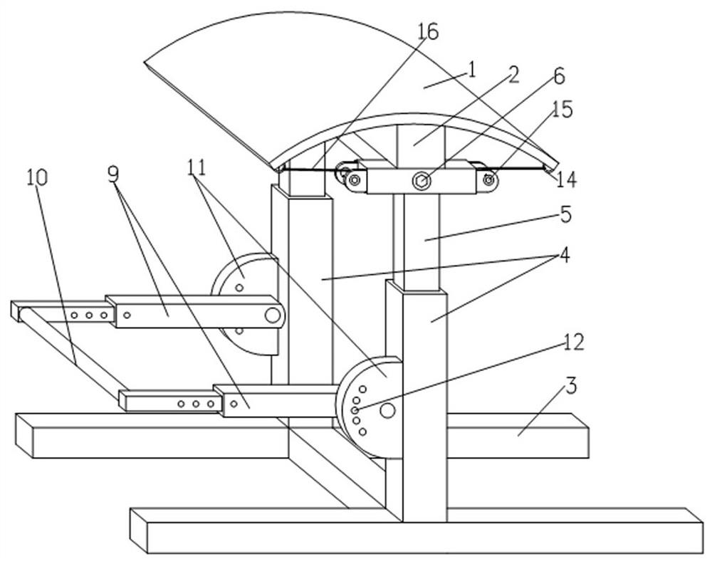
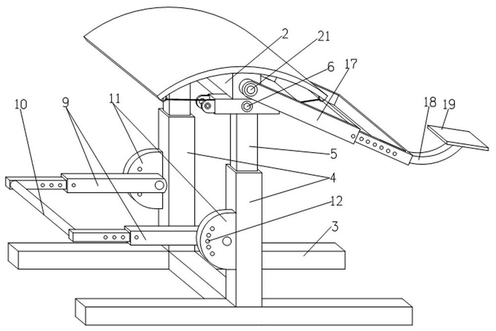
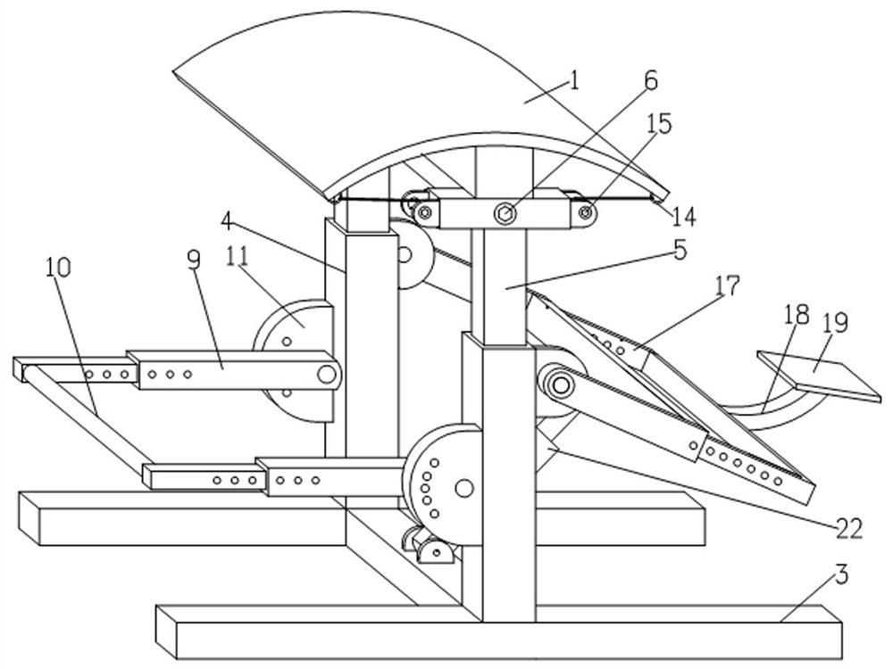
[0029] Example: see figure 1 , figure 2 , image 3 , Figure 4 and Figure 5 , in the figure, 1-waist support plate, 2-connecting beam, 3-base, 4-first bracket, 5-second bracket, 6-worm gear reducer, 7-screw, 8-nut, 9-telescopic limit Position rod, 10-limit connecting rod, 11-limit plate, 12-limit hole, 13-horizontal tube, 14-connecting ring, 15-winding wheel, 16-wire rope, 17-U-shaped telescopic frame, 18- Arc-shaped connecting rod, 19-back plate, 20-rocket switch, 21-double shaft reduction motor, 22-electrohydraulic rod, 23-transmission shaft.
[0030] A lower back device for dance training, comprising a base, a lifting bracket and a waist support plate, the waist support plate is an arc-shaped structure, the inner arc of which is axially provided with a connecting beam, the connecting beam is arranged on the base through two lifting brackets, and the lifting bracket The upper part is equipped with a foot limit frame for limiting the feet and a back support frame for s...
Embodiment 1
[0032] Embodiment one (such as figure 1 and Figure 4 ):
[0033] The lumbar support plate 1 is an arc-shaped structure, and the inner arc is axially provided with a connecting beam 2. The connecting beam 2 is arranged on the base 3 through two lifting brackets. shelf.
[0034] The lifting support includes a first support 4, a second support 5 and a lifting mechanism. One end of the lifting mechanism stretches into the first support 4, and the other end of the lifting mechanism stretches into the second support 5. The first support 4 and the second support 5 are embedded in each other. The sleeve is slidingly connected, so that the lifting mechanism is placed in the chamber formed by the first support 4 and the second support 5.
[0035]The lifting mechanism includes a worm gear reducer 6, a screw 7 and a nut 8, the worm gear reducer 6 is arranged in the second bracket 5, the input shaft of the worm gear reducer 6 extends out of the second bracket 6, and the output of the w...
Embodiment 2
[0040] Embodiment 2: This embodiment is to add the technical feature of the back support frame on the basis of Embodiment 1. The technical feature added is now described in detail (such as figure 2 , Figure 4 and Figure 5 ).
[0041] Back support frame comprises U-shaped telescopic frame 17, arc connecting rod 18 and back backing plate 19, and the open end of U-shaped telescopic frame 17 is hinged on the second support 5 by driving device, and one end of arc connecting rod 18 and back pad The plate 19 is hinged, and the other end is fixedly connected to the middle part of the closed end of the U-shaped telescopic frame 17, and the arc connecting rod 18 is provided with a ship-shaped switch 20 for controlling the driving device to work.
[0042] The driving device is a biaxial geared motor 21 arranged in the connecting beam 2 , and the rotating shaft of the biaxial geared motor 21 protrudes from the connecting beam 2 and is fixedly connected with the open end of the U-shap...
PUM
 Abstract
Description
Claims
Application Information
 - R&D
- Intellectual Property
- Life Sciences
- Materials
- Tech Scout
- Unparalleled Data Quality
- Higher Quality Content
- 60% Fewer Hallucinations
Browse by: Latest US Patents, China's latest patents, Technical Efficacy Thesaurus, Application Domain, Technology Topic, Popular Technical Reports.
© 2025 PatSnap. All rights reserved.Legal|Privacy policy|Modern Slavery Act Transparency Statement|Sitemap|About US| Contact US: help@patsnap.com


