Propylene synthesis reactor

A technology for synthesizing reactors and propylene, which is applied in the field of reactors, can solve the problems of inconvenient dispersing and adding raw materials, and achieve the effect of facilitating dispersing and adding raw materials

Inactive Publication Date: 2021-03-26
郑毅
View PDF1 Cites 0 Cited by
  • Summary
  • Abstract
  • Description
  • Claims
  • Application Information

AI Technical Summary

Problems solved by technology

But this patent is not convenient for dispersing and adding raw materials

Method used


Image

  • Propylene synthesis reactor
  • Propylene synthesis reactor
  • Propylene synthesis reactor

Examples


specific Embodiment approach 1

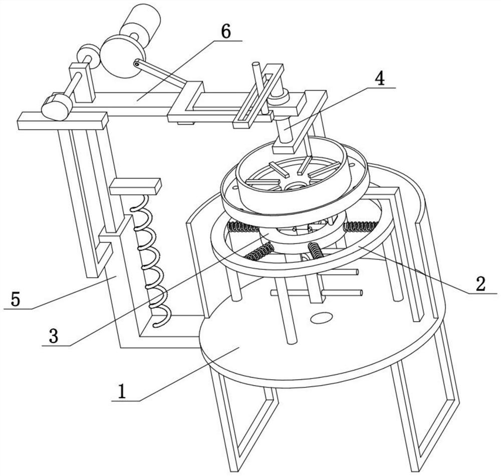
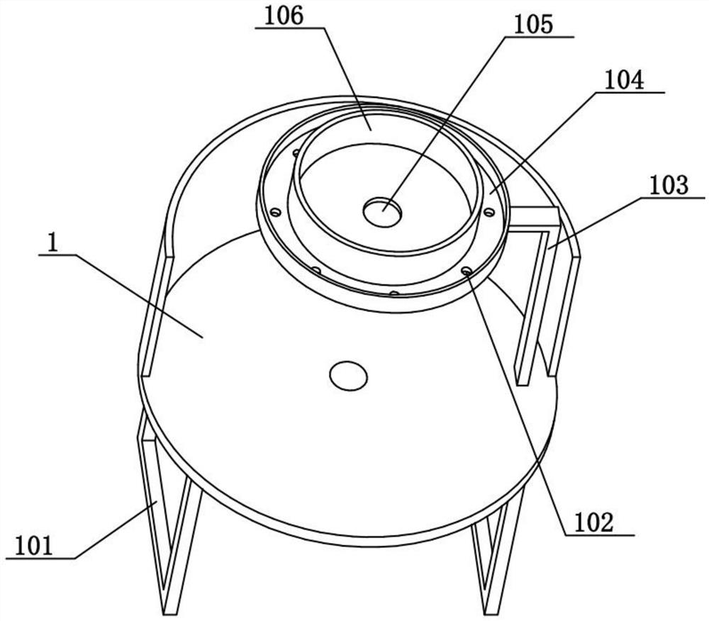
[0029] Combine below Figure 1-9 To illustrate this embodiment, the present invention relates to a reactor, more specifically a propylene synthesis reactor, comprising a reaction box 1, a bracket 101, a circular through hole 102, an L-shaped rod 103, a ring box 104, and a leak hole 105, round box 106 and heating wire 108, the present invention can be convenient to disperse and add raw material.

[0030] The left and right ends of the lower side of the reaction box 1 are fixedly connected with brackets 101, the lower side of the reaction box 1 is provided with a heating wire 108, and the lower end of the L-shaped rod 103 is fixedly connected to the edge position of the inner bottom surface of the reaction box 1. The center of the box 106 is provided with a leakage hole 105, and the outer periphery of the circular box 106 is provided with a ring box 104. The ring box 104 is provided with a plurality of circular through holes 102 in a ring shape, and the ring box 104 and the roun...

specific Embodiment approach 2

[0032] Combine below Figure 1-9 To illustrate this embodiment, the propylene synthesis reactor further includes a discharge pipe 109 , the discharge pipe 109 is provided at the lower part of the reaction box 1 , and a solenoid valve is provided on the discharge pipe 109 . The discharge pipe 109 is used for discharging, and the solenoid valve is used to control the switch of the discharge pipe 109 .

specific Embodiment approach 3

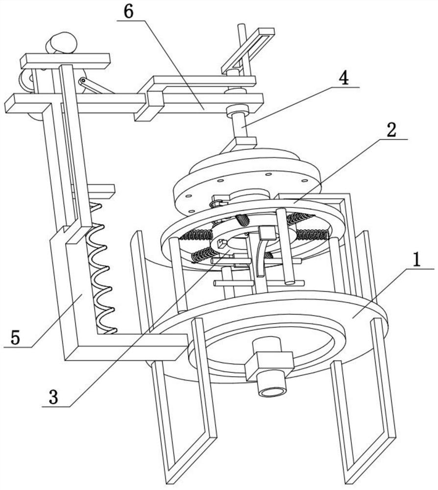
[0034] Combine below Figure 1-9To illustrate this embodiment, the propylene synthesis reactor also includes an outer ring 2, a fixed rod 201, a tension spring 1202, an inner ring 3, a horizontal shaft 301, an arc spring rod 305, a swing rod 306, and a stirring rod 307. The outer ring The lower side of the 2 is evenly distributed with a plurality of vertically arranged fixed rods 201, and the inner ring of the outer ring 2 is evenly connected with a plurality of tension springs I202, and the inner ends of the plurality of tension springs I202 are fixedly connected to the inner ring 3 On the outer peripheral surface of the inner ring 3, a horizontal shaft 301 is arranged on the inner ring, and the upper part of the swing rod 306 is rotatably connected to the middle part of the horizontal shaft 301. On the swing rod 306, a plurality of stirring rods 307 are uniformly distributed from top to bottom, and the inner ring 3. The front and rear ends of the lower side are fixedly conne...


PUM


Abstract

The invention relates to a reactor, in particular to a propylene synthesis reactor. The propylene synthesis reactor comprises a reaction box, supports, circular through holes, an L-shaped rod, a ringbox, a leakage hole, a circular box and an electric heating wire, and can be used for conveniently dispersing and adding raw materials. The supports are fixedly connected to the left end and the rightend of the lower side of the reaction box; the electric heating wire is arranged on the lower side of the reaction box; the lower end of the L-shaped rod is fixedly connected to the edge of the bottom face of the inner side of the reaction box; the leakage hole is formed in the center of the circular box; the ring box is arranged on the periphery of the circular box and annularly provided with aplurality of circular through holes; the ring box and the circular box are fixedly connected to the upper part of the L-shaped rod; and the reaction box, the ring box and the circular box are coaxially arranged. The propylene synthesis reactor also comprises a discharge pipe, wherein the lower part of the reaction box is provided with the discharge pipe, and the discharge pipe is provided with anelectromagnetic valve. The propylene synthesis reactor further comprises an outer ring, a fixing rod, an extension spring I, an inner ring, a transverse shaft, an arc-shaped elastic rod, a swing rod and a stirring rod.

Description

technical field [0001] The present invention relates to a reactor, in particular to a propylene synthesis reactor. Background technique [0002] The application number is a combined composite reaction tank disclosed in CN201921027648.2. The utility model discloses a combined composite reaction tank, including a first reaction tank and a second reaction tank, a first reaction tank and a second reaction tank The tanks are connected by connecting pipes. The tank body of the first reaction tank is provided with a first manhole, a first feed port and a first discharge port. The inside of the first reaction tank is provided with a first stirring shaft, and the top of the first reaction tank is fixedly installed. There is a first motor; the second reaction tank body is provided with a second manhole, a second feed port and a second discharge port, the second feed port is located above the top side of the second reaction tank body, and the second The material outlet is located at t...

Claims


Application Information

Patent Timeline
Patent Type & Authority Applications(China)
IPC IPC(8): B01J19/18B01J4/00B01J19/00
CPCB01J4/001B01J19/0053B01J19/18
Inventor 郑毅
Owner 郑毅
Why Eureka
Try Eureka