Fluorescent lamp tube cleaning device for stone factory

A technology for a fluorescent tube and a cleaning device, which is applied to a cleaning method using tools, a cleaning method using gas flow, and cleaning hollow objects, etc., can solve problems that affect the heat dissipation of the lamp tube, have a lot of dust, and do not have a cleaning device for the fluorescent tube, etc. , to avoid external power, increase cleaning effect, and achieve the effect of power resources

Inactive Publication Date: 2021-03-26
张辉辉
View PDF0 Cites 1 Cited by
  • Summary
  • Abstract
  • Description
  • Claims
  • Application Information

AI Technical Summary

Problems solved by technology

[0003] The existing stone factory processing workshop basically does not have a cleaning device for fluorescent tubes. During stone processing, more dust is generated, so that thicker dust is attached to the fluorescent tubes. The adhesion of dust affects the lighting effect of the fluorescent tubes. At the same time Dust adheres to the lamp tube and affects the heat dissipation of the lamp tube, thereby reducing the service life of the fluorescent lamp

Method used


Image

  • Fluorescent lamp tube cleaning device for stone factory
  • Fluorescent lamp tube cleaning device for stone factory
  • Fluorescent lamp tube cleaning device for stone factory

Examples


Embodiment 1

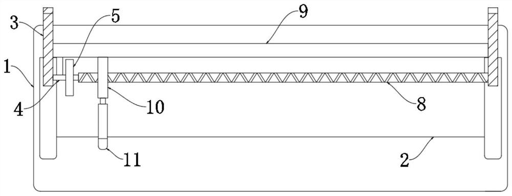
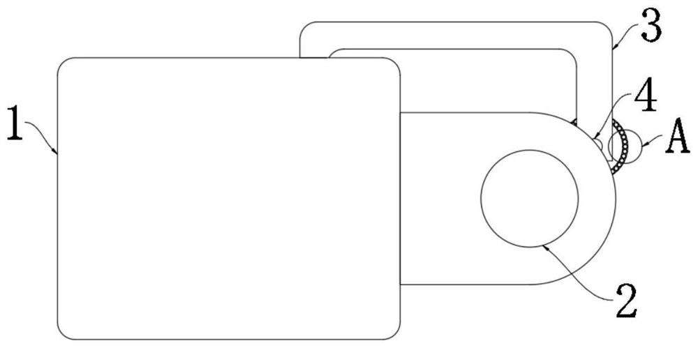
[0033] refer to Figure 1-4 , a fluorescent tube cleaning device for a stone factory, comprising a lamp holder 1, the lamp holder 1 is provided with a lamp body 2;

[0034] A pair of mounting frames 3 are fixedly connected to the lamp holder 1, a rotating shaft 4 is rotatably connected between the pair of mounting frames 3, and a fixed column 9 is fixedly connected between the pair of mounting frames 3;

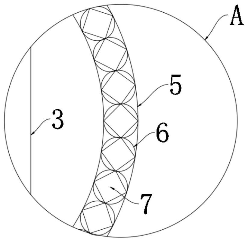
[0035] The outer wall of the rotating shaft 4 is fixedly connected with a hollow ring 5 through a plurality of connecting rods. The hollow ring 5 is provided with a plurality of heat-expandable balls 6 in contact with each other, and a plurality of heat-expandable balls 6 are embedded with counterweights 7. By setting the thermal expansion ball 6, the rotating shaft 4, the hollow ring 5, etc., the heat generated when the lamp body 2 is illuminated is converted into the power for the rotating shaft 4 to avoid external power and realize the saving of power resources. Thermal e...

Embodiment 2

[0041] refer to Figure 5-6 , a fluorescent tube cleaning device for a stone factory, the fixed column 9 is provided with an air intake cavity 13, and the air intake cavity 13 is sealed and slidably connected with a piston 14;

[0042] The right side wall of the piston 14 is fixedly connected with a magnet 15 slidably connected to the inner side wall of the air intake chamber 13, and a semicircular magnetic ring 16 is slidably connected to the outer side wall of the fixed column 9, and the semicircular magnetic ring 16 is fixedly connected with the lead screw nut 10;

[0043] The air intake end of the air intake chamber 13 communicates with the outside world, and a check valve that only allows air to enter the air intake chamber 13 from the outside world is provided at the communication point;

[0044] The cleaning ring 11 is provided with an annular chamber 17, and the side wall of the annular chamber 17 is provided with a plurality of air injection ports 18 penetrating throu...


PUM


Abstract

The invention discloses a fluorescent lamp tube cleaning device for a stone factory. The fluorescent lamp tube cleaning device comprises a lamp holder, and a lamp tube body is arranged on the lamp holder; a pair of mounting frames are fixedly connected to the lamp holder; a rotating shaft is rotatably connected between the pair of mounting frames; a fixing column is fixedly connected between the pair of mounting frames; the outer wall of the rotating shaft is fixedly connected with a hollow circular ring through a plurality of connecting rods; a plurality of thermal expansion balls making contact with one another are arranged in the hollow circular ring; balancing weights are embedded in the plurality of thermal expansion balls; the tail end of the rotating shaft is fixedly connected witha reciprocating lead screw; the reciprocating lead screw is in threaded connection with a lead screw nut slidably connected with the outer side wall of the fixing column; a cleaning ring is fixedly connected to the lead screw nut; and the inner side wall of the cleaning ring makes contact with the outer side wall of the lamp tube body. The fluorescent lamp tube cleaning device is reasonable in structure, can automatically clean a fluorescent lamp tube when a fluorescent lamp is turned on, and prevents much dust from being attached to the fluorescent lamp tube.

Description

technical field [0001] The invention relates to the technical field of lamp tube cleaning, in particular to a fluorescent lamp tube cleaning device for a stone factory. Background technique [0002] As a high-grade building decoration material, stone is widely used in indoor and outdoor decoration design, curtain wall decoration and public facilities construction. With the prevalence of stone decoration, stone factories are also developing rapidly. There are many lighting fixtures in the workshop of the stone factory. fluorescent tubes. [0003] The existing stone factory processing workshop basically does not have a cleaning device for fluorescent tubes. During stone processing, more dust is generated, so that thicker dust is attached to the fluorescent tubes. The adhesion of dust affects the lighting effect of the fluorescent tubes. At the same time The dust attached to the lamp tube affects the heat dissipation of the lamp tube, thereby reducing the service life of the f...

Claims


Application Information

Patent Timeline
Patent Type & Authority Applications(China)
IPC IPC(8): B08B1/00B08B5/02B08B9/023
CPCB08B1/002B08B1/008B08B5/02B08B9/023
Inventor 张辉辉方丹丹
Owner 张辉辉
Why Eureka
Try Eureka