Workpiece bending device

A bending device and workpiece technology, applied in the direction of feeding device, positioning device, storage device, etc., can solve the problems of high price, high labor intensity and low efficiency of bending equipment, and achieve mechanized operation, low production cost, The effect of reducing production costs

Pending Publication Date: 2021-03-26
HENAN SENYUAN ELECTRIC CO LTD
View PDF0 Cites 2 Cited by
  • Summary
  • Abstract
  • Description
  • Claims
  • Application Information

AI Technical Summary

Problems solved by technology

[0003] The purpose of the present invention is to provide a workpiece bending device, which is used to solve the problems in the prior art of small and medium-sized batches and multiple specifications of workpieces, the use of manual bending has high labor intensity, low efficiency, and high prices of mechanized bending equipment

Method used


Image

  • Workpiece bending device
  • Workpiece bending device

Examples


Embodiment Construction

[0027] The embodiments of the present invention will be further described below in conjunction with the accompanying drawings.

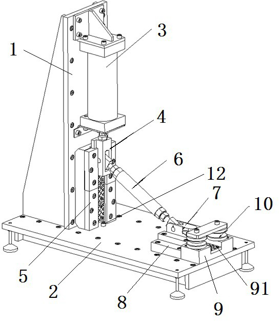
[0028] A specific embodiment of the workpiece bending device used for copper pipe bending in the present invention, such as figure 1 As shown, the workpiece bending device includes a first guide seat 1 and a second guide seat 2 arranged in an L shape; the first guide seat 1 is arranged on the second guide seat 2 . The table surface of the first guide seat 1 and the table surface of the second guide seat 2 are perpendicular to each other: the table surface of the first guide seat 1 is a vertical surface, and the table surface of the second guide seat 2 is a horizontal plane. Ribs are provided on the back of the first guide seat 1 and the second guide seat 2 , and the ribs on the second guide seat 2 form a rectangle to increase the strength of the second guide seat 2 . The reinforcing ribs of the first guide seat 1 are supported on the platform of the...


PUM


Abstract

The invention relates to a workpiece bending device. The workpiece bending device comprises a first guide seat and a second guide seat, wherein a first sliding block and a second sliding block are assembled on the first guide seat and the second guide seat respectively in a guiding mode; a driving device is arranged on the first guide seat; a pushing head is arranged on the second sliding block; aconnecting rod is arranged between the first guide seat and the second guide seat; the connecting rod has a stress application state in a moving process; an included angle between the connecting rodand the second guide seat is smaller than 45 degrees when the connecting rod is in the stress application state; when the included angle between the connecting rod and the second guide seat is smallerthan 45 degrees, the thrust of the connecting rod to the second sliding block is greater than that of the first sliding block to the connecting rod; the thrust borne by the pushing head can be greater than the output force of the driving device through the connecting rod; and when the bending force needed when bending a workpiece is not changed, the requirement on the output force of the drivingdevice of the workpiece bending device is low. The workpiece bending device can meet the production requirements of workpieces needed to be bent; and the mechanized operation is achieved.

Description

technical field [0001] The invention relates to a workpiece bending device. Background technique [0002] The high-voltage lead is an important part of the transformer, which mainly plays the role of current conduction, and is usually formed by bending a copper tube. The products of high-voltage lead wires have small batches and multiple specifications, which are not suitable for mass production. The bending process is usually done manually by workers, but manual bending has the problems of large labor and low efficiency, and the purchase price of mechanized bending equipment is relatively high. , so that the production cost of high-voltage leads is higher. Contents of the invention [0003] The object of the present invention is to provide a workpiece bending device to solve the problems in the prior art that manual bending of small and medium batches of workpieces with multiple specifications requires high labor intensity, low efficiency, and high price of mechanized be...

Claims


Application Information

Patent Timeline
Patent Type & Authority Applications(China)
IPC IPC(8): B21D7/16B21D7/06B21D43/00
CPCB21D7/06B21D7/16B21D43/003
Inventor 杨会杰孙洪宾朱海林王艳敏常霞方新穆林
Owner HENAN SENYUAN ELECTRIC CO LTD
Why Eureka
Try Eureka