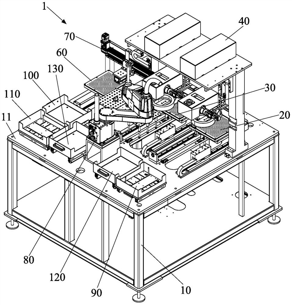
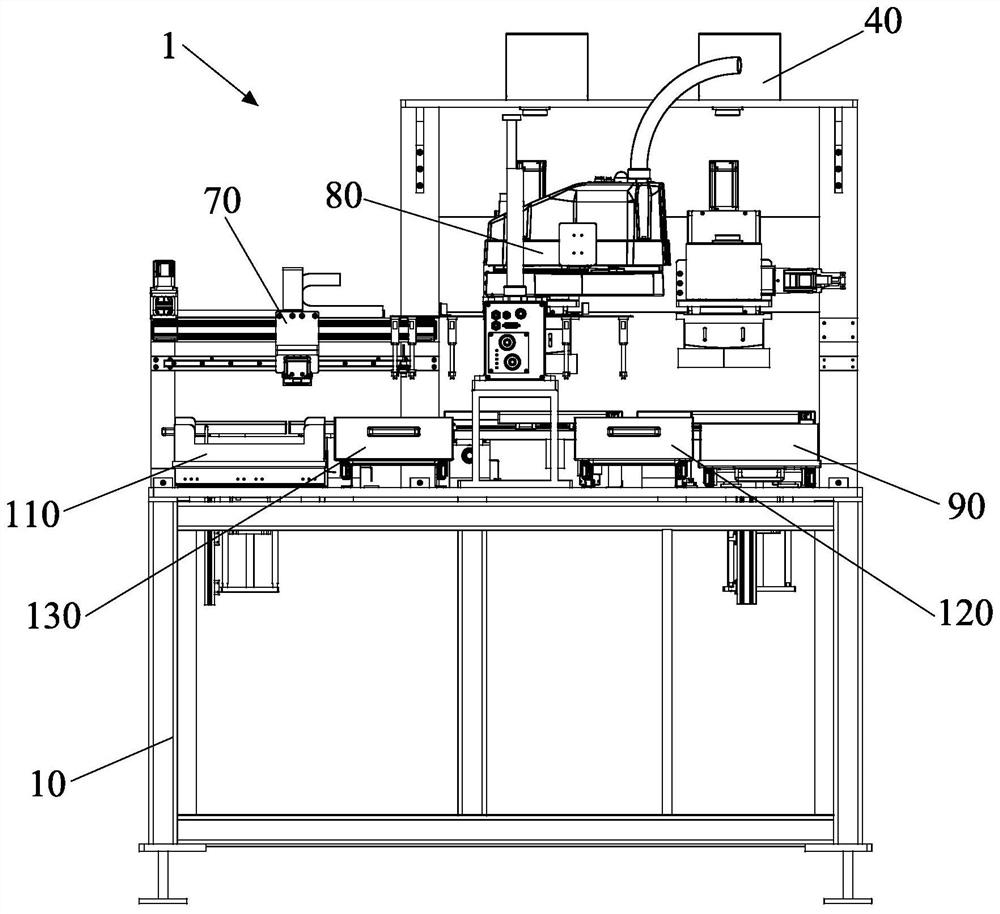
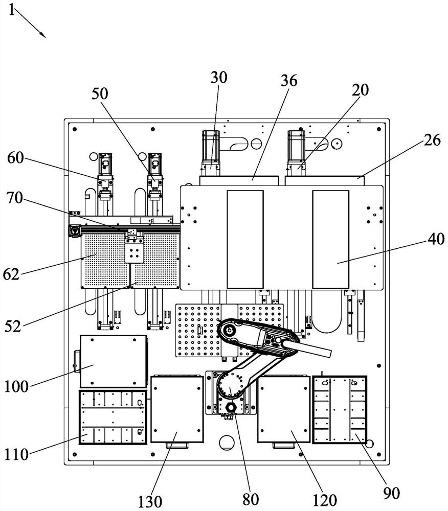
Double-station laser coding equipment and operation method thereof

A laser coding, double-station technology, applied in laser welding equipment, metal processing equipment, welding equipment and other directions, can solve the problems of low production efficiency, small processing scope, complex structure of the whole machine and so on

Pending Publication Date: 2021-03-26
厦门柔性电子研究院有限公司
View PDF0 Cites 1 Cited by
  • Summary
  • Abstract
  • Description
  • Claims
  • Application Information

AI Technical Summary

Problems solved by technology

Most of the existing laser marking machines have one station, and the production efficiency is low. There are also a few double-station laser marking machines, which operate alternately at two stations. Two sets of loading and unloading devices are set for the two stations respectively corresponding to the two stations Loading and unloading lead to complex structure of the whole machine, large equipment and high equipment unit price. There are also rotary table multi-station laser coding machines, but the structure of the rotary table is only suitable for coding small-sized products, and the scope of processing is small. And most of the existing laser coding machines or only have the laser coding function, no other functions such as scanning codes

Method used


Image

  • Double-station laser coding equipment and operation method thereof
  • Double-station laser coding equipment and operation method thereof
  • Double-station laser coding equipment and operation method thereof

Examples


Embodiment Construction

[0110] In order to further explain the technical solution of the present invention, the present invention will be described in detail below through specific examples.

[0111] In describing the present invention, it should be understood that the terms "center", "longitudinal", "transverse", "length", "width", "thickness", "upper", "lower", "front", " Back", "Left", "Right", "Vertical", "Horizontal", "Top", "Bottom", "Inner", "Outer", "Clockwise", "Counterclockwise", "X", " The orientation or positional relationship indicated by Y", "Z", etc. is based on the orientation or positional relationship shown in the drawings, and is only for the convenience of describing the present invention and simplifying the description, rather than indicating or implying that the referred device or element must have a specific orientation, are constructed and operate in a particular orientation and therefore are not to be construed as limiting the invention.

[0112] In addition, the terms "firs...


PUM


Abstract

The invention discloses double-station laser coding equipment and an operation method thereof. The equipment comprises a rack, a first coding platform mechanism, a second coding platform mechanism, alaser coding mechanism, a first code scanning platform mechanism, a second code scanning platform mechanism, a code scanning mechanism, a material moving mechanism, a product feeding mechanism and a product receiving frame. Two sets of coding platform mechanisms are adopted, and two sets of lasers and CCD galvanometer coaxial assemblies are matched, so that double-station laser coding is formed, independent control is achieved, mutual influence is avoided, two sets of single-station laser coding equipment are equivalently integrated, and the coding efficiency is greatly improved; the two setsof code scanning platform mechanisms are adopted to form double-station code scanning, one set of scanning mechanism is shared, and double stations alternately operate to scan codes, so that the working time of the scanning mechanisms is fully utilized, and the code scanning efficiency is greatly improved; The double-station laser coding equipment has the coding and scanning functions at the sametime, coding and code scanning are integrated on one piece of equipment, one code scanning procedure and one set of code scanning equipment and manpower are reduced, the production efficiency is improved, and the cost is reduced.

Description

technical field [0001] The invention relates to the technical field of laser processing, in particular to a double-station laser marking device and an operation method thereof. Background technique [0002] With the development of laser technology, more and more industries adopt laser marking instead of other marking methods such as inkjet coding, such as circuit boards, mobile phones and other consumer electronics industries. Most of the existing laser marking machines have one station, and the production efficiency is low. There are also a few double-station laser marking machines, which operate alternately at two stations. Two sets of loading and unloading devices are set for the two stations respectively corresponding to the two stations Loading and unloading lead to complex structure of the whole machine, large equipment and high equipment unit price. There are also rotary table multi-station laser coding machines, but the structure of the rotary table is only suitable ...

Claims


Application Information

Patent Timeline
IPC IPC(8): B23K26/362B23K26/70
CPCB23K26/362B23K26/70B23K26/702
Inventor 李毅峰续振林李相霖江惠荣陈妙芳黄冬荣
Owner 厦门柔性电子研究院有限公司
Why Eureka
Try Eureka