Climbing and load-bearing integrated mechanism
An integrated, shell technology, applied in building structure, hoisting device, lifting frame, etc., can solve the problems of material transportation mode blocking, hidden safety hazards, time-consuming and labor-intensive, etc., achieving simple structure, convenient and flexible use, and low cost effect
- Summary
- Abstract
- Description
- Claims
- Application Information
AI Technical Summary
Problems solved by technology
Method used
Image

Examples
Embodiment 1
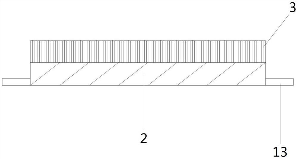
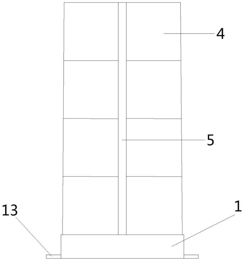
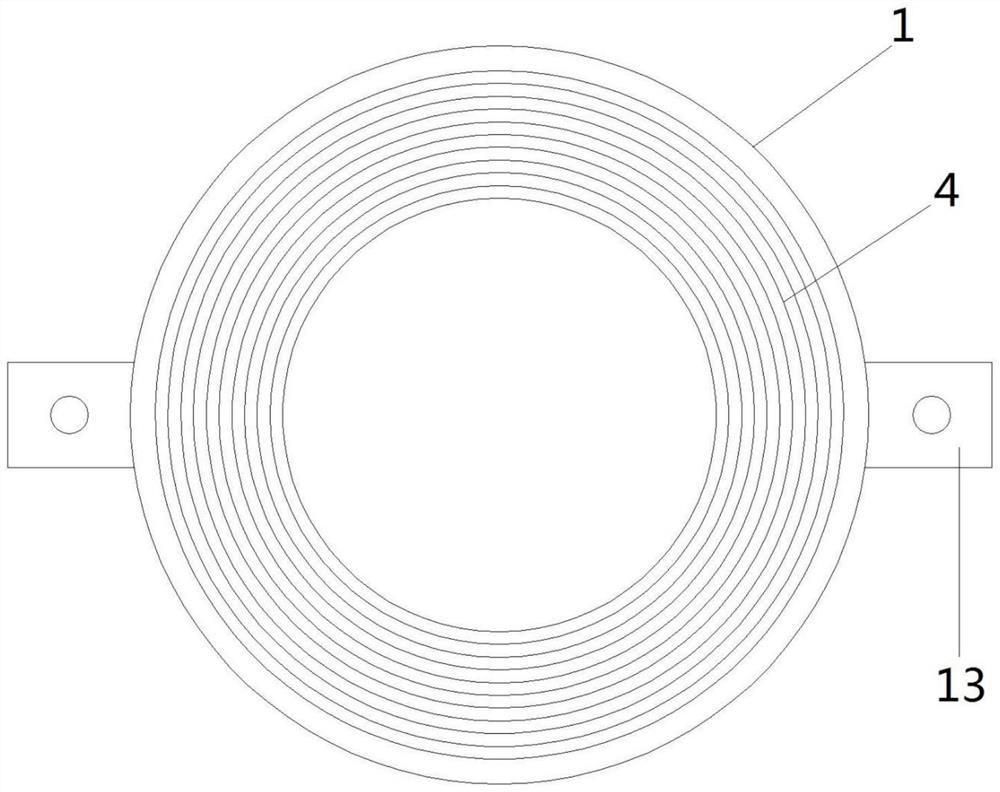
[0033] Such as Figure 1 to Figure 9 As shown, a climbing and load-bearing integrated mechanism includes a tongue post, and the tongue post includes a base 1, and a first driving device 2 is arranged inside the base 1; the output end of the first driving device 2 is connected to Cylinder suite 3, said cylinder suite 3 comprises several hollow cylindrical steel sheets 4 whose diameters decrease successively from outside to inside; the outer layer of said hollow cylindrical steel sheets 4 is provided with several rail grooves 5, and said rails The length of the groove 5 is the height of the hollow cylindrical steel sheet 4, and the inner side of the rail groove 5 is provided with the first gear set 6; it also includes a load-bearing device, and the load-bearing device includes a housing 7, the housing 7 A connecting piece 8 is arranged on the outside, and a second gear set 9 is arranged on both sides of the connecting piece 8; a second driving device 10 is arranged inside the ho...
Embodiment 2
[0036] Such as Figure 1 to Figure 9 As shown, the difference between this embodiment and Embodiment 1 is that the number of rail grooves 5 is four, which are respectively located at four tangent points where the hollow cylindrical steel sheets 4 are perpendicular to each other. By setting in this way, multiple rail grooves 5 are provided for the load-bearing device, which can facilitate installation in any direction, and multiple load-bearing devices can be used at the same time to improve efficiency.
Embodiment 3
[0038] Such as Figure 1 to Figure 9 As shown, the difference between this embodiment and the above embodiments is that the first driving device 2 and the second driving device 10 both adopt hydraulic transmission. Through such setting, a driving mode is provided for the present invention, wherein the load-bearing device makes the second driving device 10 work by means of internal drive power supply to complete the driving.
PUM
| Property | Measurement | Unit |
|---|---|---|
| Width | aaaaa | aaaaa |
Abstract
Description
Claims
Application Information