
Floating bridge structure and building method

A floating bridge and structural connection technology, applied in the direction of floating bridges, bridge construction, construction, etc., can solve the problems of a large number of manpower, lack of rapidity and mobility, and achieve the effect of reducing the demand for manpower

Active Publication Date: 2021-03-26
GUANGZHOU DESIGN & RES INST OF SHIPS & MARINE ENG
View PDF14 Cites 1 Cited by
  • Summary
  • Abstract
  • Description
  • Claims
  • Application Information

AI Technical Summary

Problems solved by technology

The modular pontoon is relatively simple, and requires a lot of manpower when building a bridge. At the same time, it needs to assist the ship to push or tow the positioning, and the speed and maneuverability are insufficient.

Method used


Image

  • Floating bridge structure and building method
  • Floating bridge structure and building method
  • Floating bridge structure and building method

Examples


Embodiment Construction

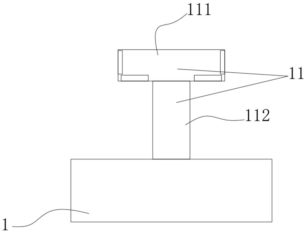
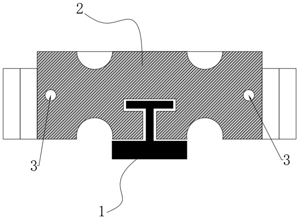
[0015] Such as figure 1 As shown, a floating bridge structure includes two positioning piles respectively arranged at both ends of the river, and a magnetic levitation track 1 is arranged between the two positioning piles. The bottom and both sides of the horizontal part 111 are provided with reaction plates and induction steel plates at intervals, and both sides of the vertical part 112 of the "T" guide rail are provided with magnetic sensors and positioning sensors; above the magnetic levitation track, multiple modules are connected end to end. The chemical buoyancy tank connects the two positioning piles to form the bridge deck; the bottom of each modular buoyancy tank is provided with a "T" groove that matches the "T" guide rail and can be embedded in the "T" guide rail; The magnet is installed on the inner wall of the "T" groove corresponding to the horizontal part of the "T" guide rail, and the positioning sensor is installed on the side wall of the "T" groove correspond...


PUM


Abstract

The invention discloses a floating bridge structure which comprises two positioning piles arranged at the two ends of the two banks of a river respectively, a magnetic suspension rail is arranged between the two positioning piles, a T-shaped guide rail is arranged on the upper portion of the magnetic suspension rail, and reaction plates and induction steel plates are arranged on the upper portionand the two sides of the horizontal portion of the T-shaped guide rail at intervals; magnetic sensors and positioning sensors are arranged on the two sides of the vertical part of the T-shaped guide rail; a plurality of modular buoyancy tanks are arranged on the magnetic levitation rail in an end-to-end connection manner to connect the two positioning piles to form a bridge floor; a T-shaped groove which is matched with the T-shaped guide rail and can embed the T-shaped guide rail is formed in the bottom of each modular buoyancy tank; magnets are mounted on the inner side walls, correspondingto the horizontal part of the T-shaped guide rail, of the T-shaped grooves, and positioning induction pieces are mounted on the side walls, corresponding to the vertical part of the T-shaped guide rail, of the T-shaped grooves; and the positioning piles and the modular buoyancy tanks and the adjacent modular buoyancy tanks are connected into a whole through self-locking bolt structures.

Description

technical field [0001] The invention relates to the technical field of floating bridges built on water, in particular to a modular floating bridge structure and a building method based on magnetic levitation technology. Background technique [0002] In the fields of tourism, traffic improvement, military emergency rescue, etc., floating bridges can be widely used as a temporary means of transportation. The structure of the existing pontoon bridge is very simple. Generally, it is only necessary to set some beams and longitudinal beams for connection and fixing on some floating objects, and then lay the bridge deck and fix them with ropes. This method is unstable in structure and easy to tip over And it is difficult to fix after the bridge deck is laid, and the operation is troublesome. Or use dozens or hundreds of boats (or rafts, bamboo rafts, or leather rafts) instead of piers, line them up in the river, use the hull as the pier, and lay beams on top as the bridge deck. ...

Claims


Application Information

Patent Timeline
IPC IPC(8): E01D15/14E01D19/00E01D19/12E01D21/00
CPCE01D15/14E01D19/00E01D19/125E01D21/00
Inventor 苏珍莉冯先伟张倩萍
Owner GUANGZHOU DESIGN & RES INST OF SHIPS & MARINE ENG
Learn More