Quantitative inflator pump

An inflatable cylinder and air cylinder technology, applied in the field of tire inflation, can solve the problems of easy occurrence of tire blowout, waste of manpower, slowing down of vehicle speed, etc.

Inactive Publication Date: 2021-03-26
刘运武
View PDF0 Cites 0 Cited by
  • Summary
  • Abstract
  • Description
  • Claims
  • Application Information

AI Technical Summary

Problems solved by technology

[0002] The way of inflating in the prior art is to determine whether it is sufficient by feeling or estimating the hardness of the tire by hand during the inflating process. Because it cannot be judged accurately, there are often too many or too few inflated phenomena, too little not only It wastes manpower and slows down the speed of the vehicle, too many tires are prone to blowout

Method used


Image

  • Quantitative inflator pump
  • Quantitative inflator pump

Examples


Embodiment Construction

[0011] Further description will be made below in conjunction with the accompanying drawings.

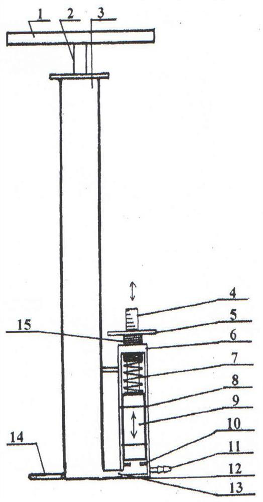
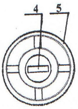
[0012] refer to figure 1 and figure 2 , the quantitative inflator is composed of the handle 2, the push rod 2, the cylinder body 3, the foot plate 14, and the jacket 6 and other components. The upper center of the jacket 6 has a screw hole (not shown) and 15 sets of hollow screws. Together, the top of the hollow screw is an outer ring 5 similar to the steering wheel, and the lower end is connected with the lower bottom plate 12 of the cylinder body 3 to be a sealed shape, and the inner edge of the lower end is connected with the gas cylinder body. The piston 9 has two ring-shaped sealing rings 8, its outer edge and the inner wall of the outer cover are close to each other, and the inner edge is close to the outer edge of the piston 9, and its upper end top of the piston is closed with The upper spring 7 sticks, and the top of the spring sticks to the top of the screw rod 15 lower ...


PUM


Abstract

The invention discloses a quantitative inflator pump, and aims to provide a tool capable of realizing manual quantitative tire inflation. According to the key points of the technical scheme of the quantitative inflator pump, an outer sleeve is arranged outside the lower end of an inflator body, a screw hole is formed in the top head at the upper end of the outer sleeve and is matched with the outer edge of a hollow screw in a threaded sleeving mode, a batten ruler with scale marks at the upper end is arranged in the space of the hollow screw, the lower end of the outer sleeve and a base plateof the inflator pump are connected into a whole to be in a sealed mode, a communicating pipeline is arranged between the inner edge of the lower end of the outer sleeve and the inflator body, a pistoncapable of ascending and descending is arranged in the middle of the outer sleeve, two to three annular sealing rings are arranged in upper and lower annular grooves in the positions, opposite to thepiston, of the inner edge of the outer sleeve, the top head of the upper end of the piston is sealed and is attached to an upper spring, the upper end of the spring is attached to the top head of thelower end of the screw, a positioning block is arranged on the inner wall of the outer sleeve at the lower position of the piston, when the air pressure in a tire rises to reach the standard air pressure in the inflation process, the piston and the batten ruler in the outer sleeve are promoted to ascend, inflation is completed, and the upper screw is screwed or unscrewed according to the requiredair pressure.

Description

technical field [0001] The invention relates to a tool for inflating tires, which is mainly used as an air pump for small tires such as bicycle tires. Background technique [0002] The way of inflating in the prior art is to determine whether it is sufficient by feeling or estimating the hardness of the tire by hand during the inflating process. Because it cannot be judged accurately, there are often too many or too few inflated phenomena, too little not only It wastes manpower and slows down the speed of the vehicle, and too many tires are prone to blowout. Contents of the invention [0003] In order to overcome the above disadvantages, the present invention aims to provide a tool capable of artificially quantifying tire inflation, which is realized by selecting the following technical solutions. [0004] A jacket is installed outside the lower end of the gas cylinder body. There is a screw hole in the center of the upper end of the jacket to fit the hollow screw rod. T...

Claims


Application Information

Patent Timeline
Patent Type & Authority Applications(China)
IPC IPC(8): F04B33/00F04B39/00
CPCF04B33/00F04B39/00
Inventor 刘运武
Owner 刘运武
Why Eureka
Try Eureka