
Compressor air suction structure, compressor and refrigeration equipment

A technology for compressors and compressor casings, which is applied in mechanical equipment, heat exchange equipment, machines/engines, etc., can solve the problems of increasing the refrigeration power consumption and energy consumption of refrigeration compressors, so as to reduce the refrigeration burden and improve the refrigeration efficiency. Effect

Pending Publication Date: 2021-03-26
HUBEI POLYTECHNIC UNIV
View PDF12 Cites 0 Cited by
  • Summary
  • Abstract
  • Description
  • Claims
  • Application Information

AI Technical Summary

Problems solved by technology

This process consumes energy to a considerable extent, increasing the cooling power consumption of the refrigeration compressor

Method used


Image

  • Compressor air suction structure, compressor and refrigeration equipment
  • Compressor air suction structure, compressor and refrigeration equipment
  • Compressor air suction structure, compressor and refrigeration equipment

Examples


Embodiment Construction

[0026] In order to facilitate the understanding of the present invention, the present invention will be described more fully below with reference to the associated drawings. Possible embodiments of the invention are shown in the drawings. However, the present invention can be implemented in many different forms and is not limited to the embodiments which have been described herein with reference to the drawings. The embodiments described by referring to the accompanying drawings are exemplary for making the disclosure of the present invention more thorough and comprehensive, and should not be construed as limiting the present invention. Furthermore, if detailed descriptions of known technologies are not technically essential to the illustrated features of the invention, such technical details may be omitted.

[0027] Those skilled in the relevant art can understand that, unless otherwise defined, all terms (including technical terms and scientific terms) used herein have the ...


PUM

PropertyMeasurementUnit
Axial lengthaaaaaaaaaa

Abstract

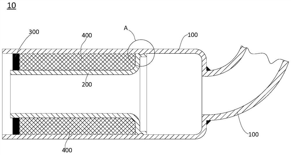
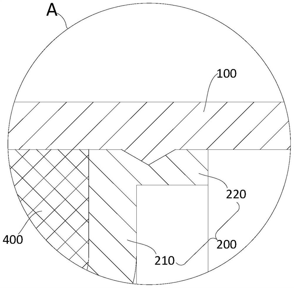
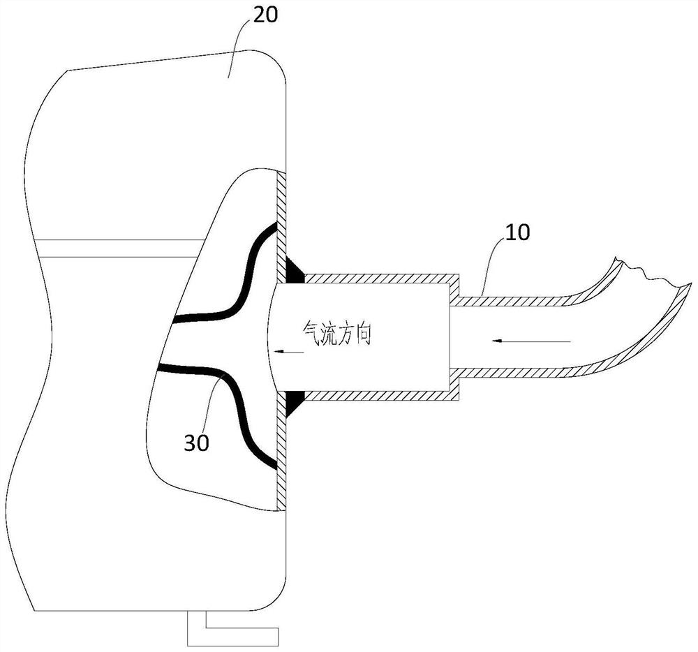
The invention relates to a compressor air suction structure, a compressor and refrigeration equipment. The compressor air suction structure comprises an air suction pipe, an inner cylinder, a sealingring and a heat insulation filling part, wherein the outer side wall of the first end of the inner cylinder is connected with the inner side wall of the air suction pipe in a buckled mode; the sealingring is arranged between the outer side wall of the second end of the inner cylinder and the inner side wall of the air suction pipe; and the heat insulation filling part is arranged in a space formed by the sealing ring, the air suction pipe and the inner cylinder. According to the compressor air suction structure provided by the invention, an original air suction pipe with an independent pipe type structure is changed into a composite structure with the inner cylinder and a heat insulation layer, and heat on a compressor shell is isolated on an outer pipe of the air suction pipe through thecomposite structure with the heat insulation layer at a certain length, so that the temperature of the inner cylinder of the air suction pipe is low, gas entering the compressor through the inner cylinder is prevented from being heated, the refrigeration burden of the compressor is effectively relieved, and the refrigeration efficiency of the compressor is improved.

Description

technical field [0001] The invention relates to the field of refrigeration equipment, in particular to a compressor suction structure, a compressor and refrigeration equipment. Background technique [0002] More and more people pay more and more attention to the refrigeration efficiency of compressors in refrigeration equipment. Obtaining more cooling capacity with the same energy consumption has always been the tireless technical pursuit of refrigeration compressors. With the optimized design of various aspects such as mechanical structure and control mode, the energy efficiency level of refrigeration compressors in the prior art has reached a relatively high level, and it is becoming more and more difficult to further improve energy efficiency. [0003] In the actual operation of life or engineering, the refrigeration equipment, such as the compressor of the refrigerator, continues to work and continuously emits heat, and the temperature of the outer casing can reach 60-70...

Claims


Application Information

Patent Timeline
IPC IPC(8): F04B39/12F04B39/06F16L59/02
CPCF04B39/123F04B39/06F16L59/029
Inventor 蔺绍江罗静王强吴振鹏王向杰陈国兴
Owner HUBEI POLYTECHNIC UNIV
Learn More