LED daylight lamp device capable of directly replacing fluorescent lamp

A technology of LED fluorescent lamps and LED lamps, applied in the field of lighting, can solve the problem of difficulty in replacing power supplies, and achieve the effects of reducing the burden of heat dissipation, emitting light without shadows, and saving recycling costs

Inactive Publication Date: 2013-12-04
徐慧
View PDF10 Cites 0 Cited by
  • Summary
  • Abstract
  • Description
  • Claims
  • Application Information

AI Technical Summary

Problems solved by technology

[0005] But this LED fluorescent lamp with built-in power supply has the following disadvantages: (1) It is difficult to replace the power supply
Although the LED fluorescent lamp with an external LED power supply solves some defects of the built-in power supply, the installation of the power supply needs to change the original circuit in order to fix it on the light board of the traditional fluorescent lamp

Method used


Image

  • LED daylight lamp device capable of directly replacing fluorescent lamp
  • LED daylight lamp device capable of directly replacing fluorescent lamp
  • LED daylight lamp device capable of directly replacing fluorescent lamp

Examples


Embodiment 1

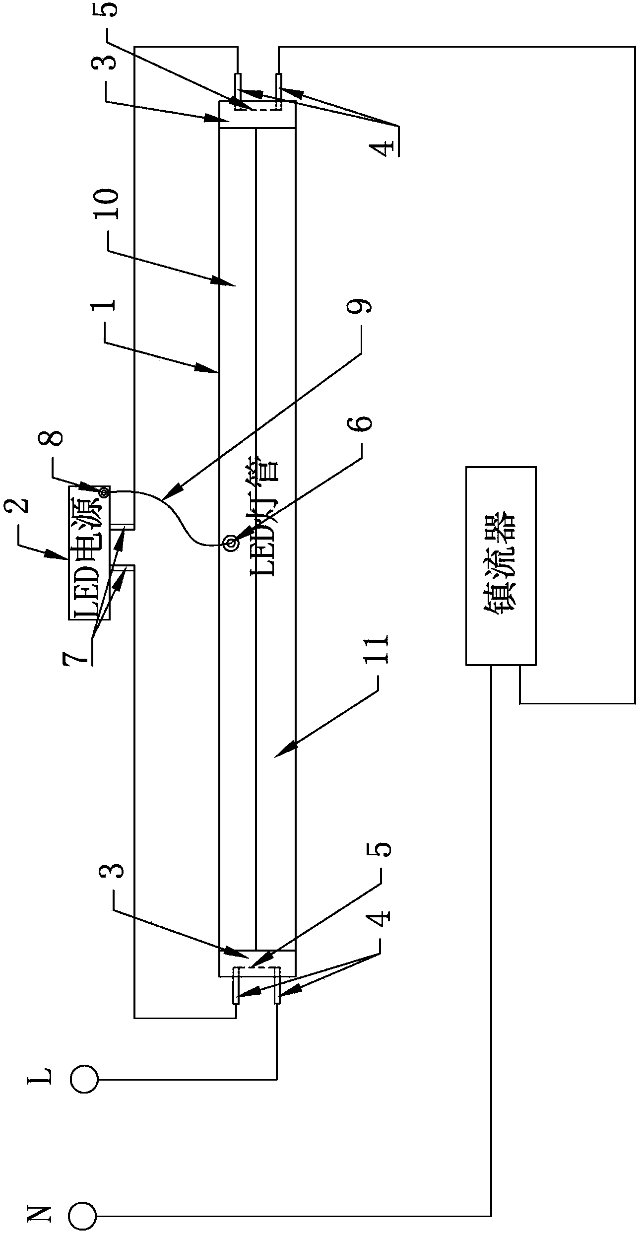
[0050] A kind of LED fluorescent lamp device that can directly replace the fluorescent lamp of this embodiment such as Figure 1 to Figure 4 As shown, it includes an LED light tube 1 and an external LED power supply 2. The two ends of the LED light tube 1 are respectively connected to end caps 3, and the end cap 3 is provided with two terminals 4. The terminal 4 includes a The inner end on the inner side and the outer end on the outer side of the end cover 3 are short-circuited between the inner ends of the two terminals 4 on the same end cover 3 through a conductive member 5 , and the lamp tube 1 is provided with a DC input end 6 .

[0051] The external LED power supply 2 is provided with a starter interface terminal 7 and a DC output terminal 8 . The external LED power supply 2 with the starter interface terminal 7 can be directly installed at the position of the starter, which is convenient for maintenance or replacement. The provided DC output terminal 8 can provide drivi...

Embodiment 2

[0062] An LED fluorescent lamp device that can directly replace fluorescent lamps. The other structures of this embodiment are the same as those of Embodiment 1, except that the inner ends of the two terminals 4 are short-circuited through a conductive sheet. The use of conductive sheets can facilitate production and processing.

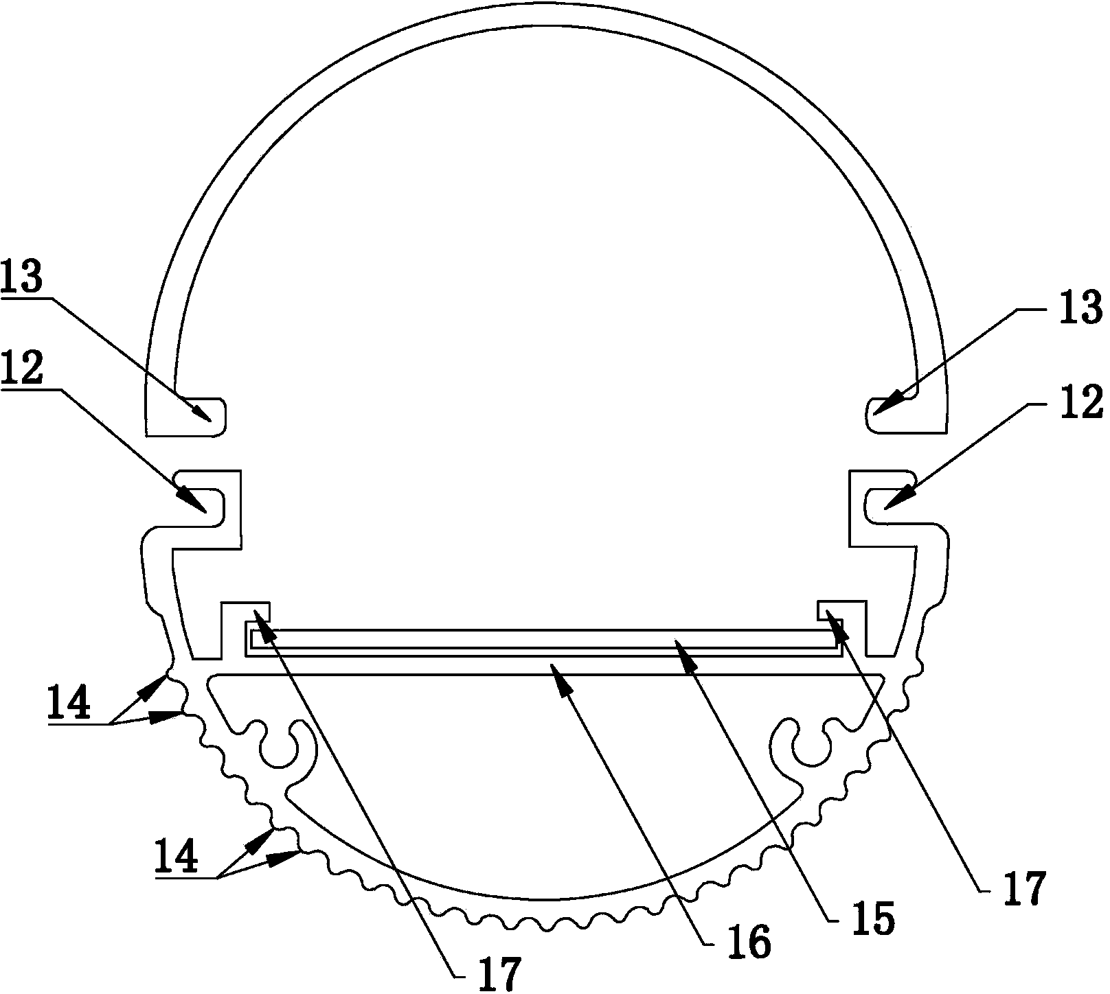
[0063] The LED lamp tube 1 includes a radiator 10 and a lampshade 11, and the radiator 10 and the lampshade 11 are connected to each other to form a hollow cylindrical LED lamp tube. The appearance of the LED lamp tube 1 is basically the same as that of the fluorescent lamp, which can better match the original lamp holder of the fluorescent lamp.

[0064] The radiator 10 and the lampshade 11 are fastened together to form a hollow cylindrical LED lamp tube. The mounting or dismounting of the radiator 10 and the lampshade 11 is facilitated by buckling.

[0065] The radiator 10 is uniformly provided with cooling fins 14 . The heat sink 14 is used to ...

Embodiment 3

[0067] An LED fluorescent lamp device that can directly replace fluorescent lamps. The other structures of this embodiment are the same as those of Embodiment 1, except that the inner ends of the two terminals 4 are short-circuited by wires. Using a wire as the conductive member 5 has better wire performance and saves cost.

[0068] The radiator 10 is provided with a groove 12 , and the lampshade 11 is provided with a protruding strip 13 , and the protruding strip 13 is matched with the groove 12 . The fastening method of the protruding strip 13 and the groove 12 facilitates the installation and disassembly of the radiator 10 and the lampshade 11 , and facilitates the replacement or maintenance of the LED light source assembly 15 in the LED lamp tube 1 . It should be noted that other fastening methods can also be designed according to actual needs, and are not limited to the matching connection method between the convex strip 13 and the groove 12 .

[0069] The LED lamp tube ...


PUM


Abstract

An LED daylight lamp device capable of directly replacing a fluorescent lamp comprises an LED lamp tube (1) and an external LED power supply (2). Two ends of the LED lamp tube (1) are connected to end covers (3) respectively. Inner ends of two terminals (4) disposed in the same end cover (3) are mutually shorted through a conductive member (5). A DC input end (6) is further disposed on the LED lamp tube (1). A starter interface terminal (7) and a DC output end (8) are disposed on the external LED power supply (2). The DC output end (8) is electrically connected to the DC input end (6) in a removable manner through a power line (9). The external LED power supply (2) can be directly mounted at the position of the original starter, and fit an interface of the original starter. The LED lamp tube (1) can be directly mounted at the position of the original fluorescent lamp. Therefore, the LED power supply (2) and the LED lamp tube (1) can be fast replaced without changing any circuit. In addition, as the LED power supply (2) is externally provided, the LED daylight lamp device easily meets the safety regulations and standards, and the light quality is high.

Description

technical field [0001] The invention relates to the technical field of lighting, in particular to an LED fluorescent lamp device which can directly replace fluorescent lamps. Background technique [0002] Traditional fluorescent tubes are also called fluorescent lamps, such as image 3 As shown, there is a filament at each end of the lamp tube. The lamp tube is filled with a small amount of argon and thin mercury vapor. The inner wall of the lamp tube is coated with phosphor powder. When the gas between the two filaments conducts electricity, it emits ultraviolet rays, making the phosphor powder emit Visible light, due to the heavy metal pollutant "mercury", makes the scrapped fluorescent tubes pollute the environment very seriously. [0003] The LED fluorescent lamp uses light-emitting diodes as the light source, which has higher light efficiency, more energy saving, longer service life, and is more environmentally friendly. LED fluorescent lamps save electricity by more t...

Claims


Application Information

Patent Timeline
Patent Type & Authority Patents(China)
IPC IPC(8): F21S2/00F21V23/06F21V17/16F21Y101/02
CPCF21V29/004F21K9/17F21K9/27F21V29/70F21Y2115/10
Inventor 徐慧
Owner 徐慧
Why Eureka
Try Eureka