
Optical detection method and device for milling surface machining quality control

An optical detection and surface processing technology, applied in the field of milling surface processing, can solve the problems of poor material detection accuracy, no material clamping and fixing, and easy sliding displacement of materials, so as to prevent clamping damage and improve detection accuracy. Effect

Pending Publication Date: 2021-03-26
SHENZHEN KING TEAM PRECISION TECH
View PDF0 Cites 0 Cited by
  • Summary
  • Abstract
  • Description
  • Claims
  • Application Information

AI Technical Summary

Problems solved by technology

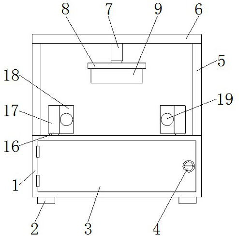
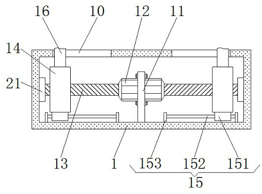
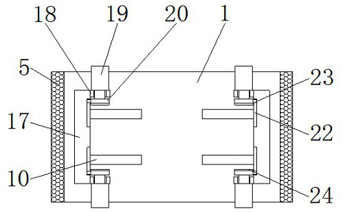
[0005] The object of the present invention is to provide an optical detection method and device for quality control of milling surface processing, which has the advantage of clamping and fixing materials, and solves the problem that existing optical detection devices do not have the function of clamping and fixing materials. As a result, when the optical detection device detects the material, the material is prone to sliding displacement, resulting in poor detection accuracy of the material

Method used


Image

  • Optical detection method and device for milling surface machining quality control
  • Optical detection method and device for milling surface machining quality control
  • Optical detection method and device for milling surface machining quality control

Examples


Embodiment Construction

[0025] Next, the technical solutions in the embodiments of the present invention will be apparent from the embodiment of the present invention, and it is clearly described, and it is understood that the described embodiments are merely embodiments of the present invention, not all of the embodiments. Based on the embodiments of the present invention, there are all other embodiments obtained without making creative labor without making creative labor premises.

[0026] In the description of the present application, it is to be understood that the terms "center", "upper", "lower", "front", "post", "left", "right", "vertical", "horizontal" , "Top", "bottom", "inside", "outside", etc. The orientation or location relationship is based on the orientation or positional relationship shown in the drawings, is only for convenience of description of this patent and simplified description, not an indication or I suggest that the device or component must have a specific orientation, constructe...


PUM


Abstract

The invention discloses an optical detection method and a device for milling surface processing quality control, and the device comprises a box body, four corners of the bottom of the box body are fixedly connected with supporting legs, the front surface of the box body is movably connected with a box door through a movable pin, and the right side of the front surface of the box door is fixedly provided with a door lock. Vertical plates are fixedly connected to the two sides of the top of the box body, and a top plate is fixedly connected to the tops of the vertical plates. Through mutual cooperation of sliding groove, a fixing plate, a stepping motor, a threaded rod, a threaded block, an anti-shaking mechanism, a sliding rod, a clamping plate, a limiting plate, a second air cylinder, a clamping plate, a bearing, a sliding groove, a sliding block and a buffer pad, the advantage of clamping and fixing materials is achieved, and when the optical detection device detects the materials, the materials can be effectively clamped, fixed and limited, the detection accuracy of the materials is improved, meanwhile, the detection accuracy of the optical detection device is improved, and the use requirements of users can be met.

Description

Technical field [0001] The present invention relates to the field of milling surface processing, and is specifically an optical detection method and apparatus for milling surface processing mass control. Background technique [0002] The CNC lathe can be processed by complex rotary body shape. Milling is fixed to the blank, and the cutter of high-speed rotation is taken on the blank, cut out the needs of the shape and characteristics, and the traditional milling is more useful for milling profiles and grooves. Simple The shape characteristics, the CNC milling machine can be processed by complex shape and characteristics, and the milling process center can perform three-axis or multi-shaft milling process for processing, mold, inspection, carotes, thin-walled surface, artificial prosthesis, Leaves, etc., when choosing CNC milling processing, the advantages and key roles of the CNC milling machine should be given to. [0003] Optical measurement of glass materials for manufacturing...

Claims


Application Information

Patent Timeline
Patent Type & Authority Applications(China)
IPC IPC(8): G01N21/84G01N21/01B25B11/00
CPCG01N21/84G01N21/01B25B11/00
Inventor 吴春谅
Owner SHENZHEN KING TEAM PRECISION TECH
Learn More