
Laser radar system based on wireless communication network and working method thereof

A wireless communication and lidar technology, applied in the field of unmanned aerial vehicles, can solve the problems of weak reception of returned optical signals, inability to transmit and monitor lidar data in real time, etc.

Pending Publication Date: 2021-03-26
STATE GRID INTELLIGENCE TECH CO LTD
View PDF21 Cites 0 Cited by
  • Summary
  • Abstract
  • Description
  • Claims
  • Application Information

AI Technical Summary

Problems solved by technology

[0006] In order to solve the above problems, the present invention proposes a laser radar system based on a wireless communication network and its working method. Through the rotation of the beam splitter and the reflector in the optical assembly, the laser emitted by the laser emitter is shot onto the target object, and the The returned optical signal is sent to the signal receiver, which solves the technical problem in the prior art that the signal receiving position is fixed and the receiving ability of the returned optical signal is weak; at the same time, the laser radar data is transmitted back to the central server in real time through the wireless communication network data transmission component, solving the problem of Technical problems existing in the existing technology that cannot transmit and monitor lidar data in real time

Method used


Image

  • Laser radar system based on wireless communication network and working method thereof
  • Laser radar system based on wireless communication network and working method thereof
  • Laser radar system based on wireless communication network and working method thereof

Examples


Embodiment 1

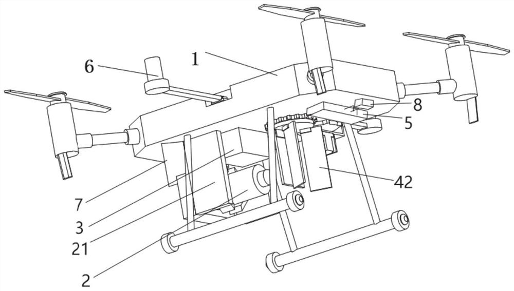
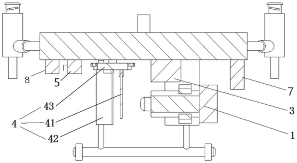
[0032] Such as Figure 1-2 As shown, the present embodiment provides a laser radar system based on a wireless communication network, including a drone body 1, and an optical assembly 4, a laser transmitter 2, a signal receiver 3 and a wireless Communication network data transmission component 5;

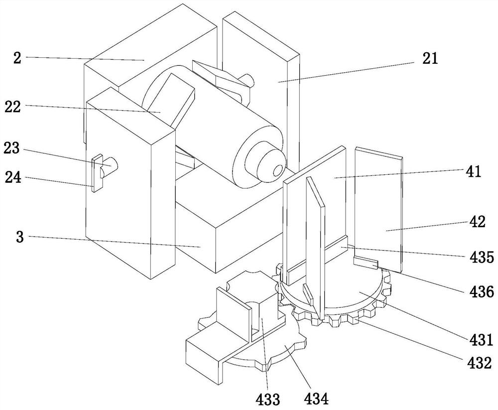
[0033] The optical assembly 4 is located at the excitation end of the laser transmitter 2 and the receiving end of the signal receiver 3. The optical assembly 4 includes a beam splitter 41, a reflector 42 and a displacement member 43, and the displacement member 43 drives the beam splitter 41 and the displacement member 43. The reflector 42 rotates to shoot the laser light emitted by the laser transmitter 2 onto the target object, and transmit the returned optical signal to the signal receiver 3, and the wireless communication network data transmission component 5 transmits the optical signal received by the signal receiver 3 It is transmitted to the central server through the wirel...


PUM


Abstract

The invention discloses a laser radar system based on a wireless communication network and a working method thereof. The laser radar system comprises an unmanned aerial vehicle, and optical assemblies, a laser emitter, a signal receiver and a data transmission assembly which are arranged on the unmanned aerial vehicle, wherein the optical assembly is located at the excitation end of the laser emitter and the receiving end of the signal receiver, the optical assembly comprises a spectroscope, a reflector and a displacement piece, and the displacement piece drives the spectroscope and the reflector to rotate so as to emit laser emitted by the laser emitter to a target object and emit a returned optical signal to the signal receiver. And the data transmission assembly transmits the optical signals received by the signal receiver to a central server through a wireless communication network. The technical problem that in the prior art, the signal receiving position is fixed, and consequently the returned light signal receiving capacity is poor is solved, and the technical problem that in the prior art, laser radar data cannot be transmitted and monitored in real time is solved.

Description

technical field [0001] The invention relates to the technical field of unmanned aerial vehicles, in particular to a laser radar system based on a wireless communication network and a working method thereof. Background technique [0002] The statements in this section merely provide background information related to the present invention and do not necessarily constitute prior art. [0003] Airborne lidar optical scanning is a new type of active multi-sensor integrated complex system. The terrain model makes it have unique advantages in the fields of terrain surveying and mapping, digital city modeling, forest survey, disaster monitoring, environmental monitoring and so on. [0004] However, the inventors found that the traditional laser radar optical scanning is not stable enough when it is connected to the airborne, and it is easily affected by the flight angle of the fuselage during flight, which affects the overall scanning results, and the laser radar optical scanning i...

Claims


Application Information

Patent Timeline
IPC IPC(8): G01S17/02G01S7/481
CPCG01S17/02G01S7/481
Inventor 张飞刘俍刘天立韩铠泽魏传虎周长明刘越高绍楠赵金龙周大洲马晓锋李缘张毅
Owner STATE GRID INTELLIGENCE TECH CO LTD
Learn More