An outdoor power distribution cabinet

A power distribution cabinet and outdoor technology, applied in substation/power distribution device casing, electrical components, door/window accessories, etc., can solve problems such as inconvenient operation, inability to effectively block rain, troubles, etc., and achieve the effect of improving convenience

Active Publication Date: 2022-07-22
深圳市新能电气有限公司
View PDF6 Cites 0 Cited by
  • Summary
  • Abstract
  • Description
  • Claims
  • Application Information

AI Technical Summary

Problems solved by technology

[0004] The power distribution cabinet avoids the accident of accidental electric shock when the maintenance personnel operate by setting the inner and outer doors, but the inventor believes that there are still the following defects: since the inner and outer doors are locked and fixed by locking, the outer door is locked. It avoids electric shock caused by outsiders opening the power distribution cabinet at will. Generally, only the maintenance personnel can have the corresponding key to open the outer door, and the setting of the inner door is mainly for the maintenance personnel to repair the components between the inner door and the outer door. At the same time, the power distribution cabinet can prevent rain when the cabinet door is closed, but if it is necessary to overhaul the inside of the power distribution cabinet in rainy days, the cabinet door needs to be opened, and the cabinet door is opened It cannot effectively block the rain, and maintenance personnel need to carry out maintenance work with an umbrella, which is inconvenient to operate

Method used


Image

  • An outdoor power distribution cabinet
  • An outdoor power distribution cabinet
  • An outdoor power distribution cabinet

Examples


Embodiment Construction

[0040] Attached to the following Figure 1-8 This application will be described in further detail.

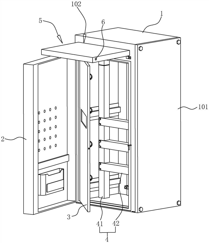
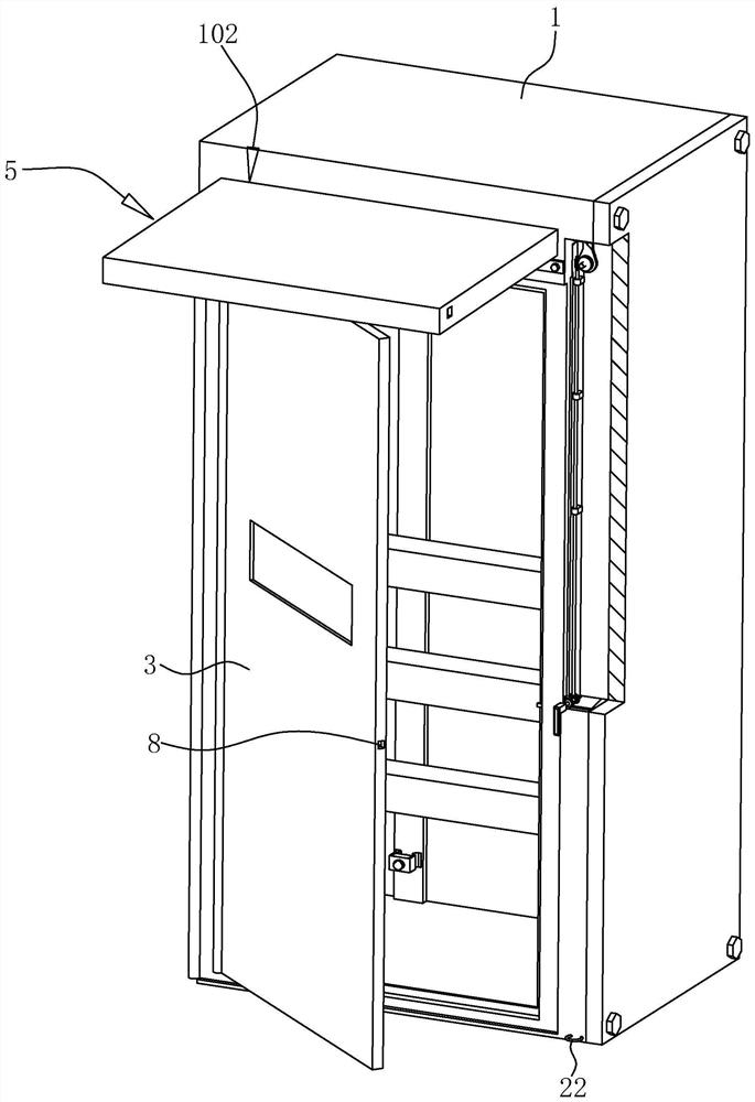
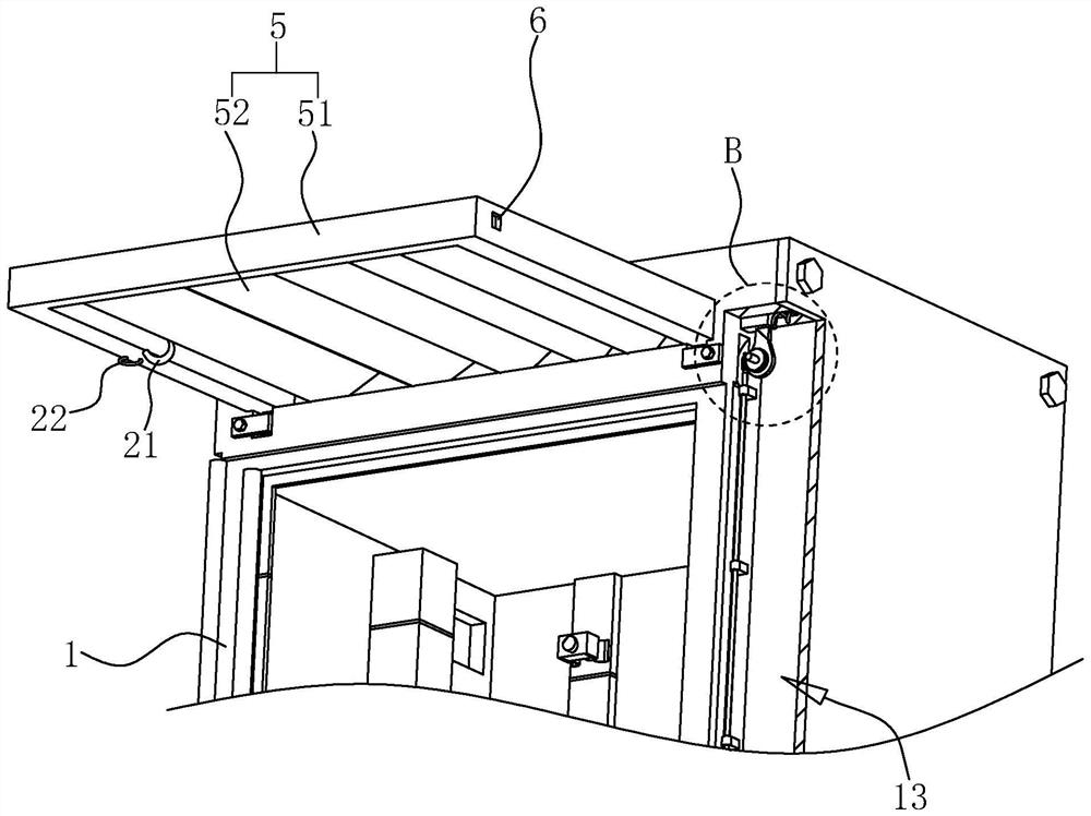
[0041] The embodiments of the present application disclose an outdoor power distribution cabinet. refer to figure 1 and figure 2 , which includes a cuboid-shaped cabinet 1 and an outer door 2 and an inner door 3 pivotally connected to the open side of the cabinet 1 from outside to inside, and an outer door 2 lock is installed between the outer door 2 and the cabinet 1 . At the same time, a mounting frame 4 is fixedly installed inside the cabinet body 1 . Specifically, the mounting frame 4 includes a pair of vertical columns 41 parallel to each other and a plurality of cross bars fixedly connected between the two columns 41 by screws. 42 , the plurality of horizontal bars 42 are arranged horizontally, and the plurality of horizontal bars 42 are distributed at equal intervals along the length direction of the upright column 41 . In addition, a plurality of screw holes (not s...


PUM


Abstract

The present application relates to the technical field of electrical equipment, in particular to an outdoor power distribution cabinet. The main points of the technical solution are: a cabinet body, an outer door and an inner door, and an outer door lock is arranged between the outer door and the cabinet body. The upper end side of the open side of the cabinet is laterally provided with a accommodating cavity, the accommodating cavity is slidably connected with a rain shield that can be retracted and protruded from the accommodating cavity, the side wall of the rain shield is provided with a positioning hole, and the cabinet body is movable with locking The positioning piece of the rain shield, when the positioning piece is locked in the positioning hole, the rain shield is fixed in the accommodating cavity; the free end of the inner door is provided with a lock hole, the side wall of the cabinet is laterally provided with a chute, one end of the chute The opening is extended to the inner cavity of the cabinet, the chute is slidably connected with a locking piece, and the cabinet body is respectively provided with a driving assembly and a linkage mechanism for driving the positioning piece and the locking piece to unlock synchronously. The present application enables the staff to conveniently open the inner door on rainy days and perform maintenance work on the power distribution cabinet without holding an umbrella.

Description

technical field [0001] The present application relates to the technical field of power distribution equipment, in particular to an outdoor power distribution cabinet. Background technique [0002] The power distribution cabinet is a common power control equipment. The low-voltage power distribution cabinet is used for power conversion and control of lighting and power distribution, and has a wide range of applications. The shell structure of the low-voltage cabinet directly affects the on-site installation of power to a large extent. With the current various forms of power construction, whether the on-site construction and installation of the low-voltage power distribution cabinet is convenient greatly affects the investment of resources in power construction. [0003] For example, the Chinese patent with the publication number CN203800414U in the related art discloses an electric shock-proof double-door power distribution cabinet, which includes a cabinet body and a double-...

Claims


Application Information

Patent Timeline
Patent Type & Authority Patents(China)
IPC IPC(8): H02B1/28H02B1/30H02B1/32E05B65/52E05B3/00E05B15/00
CPCH02B1/28H02B1/306H02B1/32E05B65/00E05B3/00E05B15/00
Inventor 张清文李凯龙王莉蓉
Owner 深圳市新能电气有限公司
Why Eureka
Try Eureka