Stator structure and its manufacturing method

A stator structure and stator punching technology, which is applied in the manufacture of motor generators, stator/rotor bodies, magnetic circuit shapes/styles/structures, etc., can solve problems such as reducing the size of the motor and limited space for multi-pole windings, and achieve material Small amount of use, easy to ensure the position of the full circle structure, and the effect of less winding waste

Active Publication Date: 2021-06-01
BEIJING BOLKEN EQUIP +1
View PDF7 Cites 0 Cited by
  • Summary
  • Abstract
  • Description
  • Claims
  • Application Information

AI Technical Summary

Problems solved by technology

[0006] The invention provides a stator structure, which adopts H-shaped winding slots, and the windings are wound directly facing the center line of the slots, so as to realize the function of forming a circumferential tangential N / S pole at the spatial position of a slot, saving the amount of silicon steel sheet and winding copper wire, and saving the space of the motor , reduce the size of the motor, and solve the problem of limited space for the multi-pole winding of the motor

Method used


Image

  • Stator structure and its manufacturing method
  • Stator structure and its manufacturing method
  • Stator structure and its manufacturing method

Examples


Embodiment 1

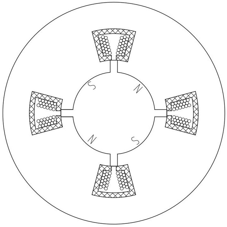
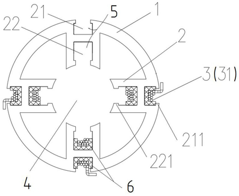
[0030] A stator structure such as image 3 As shown, it includes a yoke 1 and four teeth 2 distributed symmetrically along the center of the yoke 1, the teeth 2 are H-shaped structure teeth 2 arranged along the radial direction of the yoke 1, one of the The outer slot hole 21 and the inner slot hole 22 of the H-shaped tooth 2 jointly form a wire slot 5 for the winding coil 31 . Wires are respectively wound in the wire groove 5 formed by the outer slot 21 and the inner slot 22 of each H-shaped structure tooth 2 to form a motor winding 3, that is, a winding coil 31 is wound on an H-shaped structure tooth 2, The four winding coils 31 together form the motor winding 3. When the motor winding 3 is energized, the spatial position of an H-shaped structure tooth 2 forms two magnetic poles N and S tangential to the circumference of the stator structure; that is, when the yoke 1 has four When the tooth part 2 (H-shaped structure teeth), can generate 8 magnetic poles, it can obtain the ...

Embodiment 2

[0036] A manufacturing method of the above-mentioned stator structure includes the steps of punching out H-shaped structural teeth 2 on a cylindrical body or a plate body with a full circular structure, or directly casting them.

[0037] After forming, it is preferable to insert the plug-in type insulating card 6 relatively along its axial direction in the outer slot hole 21 and the inner slot hole 22 of each H-shaped structure tooth 2, and then insert the plug-in type insulating card 6 in the ring shape of each said plug-in type insulating card 6. A winding is wound in the slot along the axial direction of the stator structure; finally, each winding coil is welded to a corresponding position of the control board.

Embodiment 3

[0039] Different from the above-mentioned embodiments, the stator structure includes a plurality of stator punching pieces stacked on each other along the axial direction of the stator structure, each of the stator punching pieces includes the yoke portion 1 and the tooth portion 2 , the H-shaped structure teeth 2 of each of the stator punches are correspondingly overlapped to form a wire slot 5 .

[0040] A method for manufacturing the above-mentioned stator structure, comprising the steps of punching out H-shaped structure teeth 2 and the yoke portion 1 on a full-circle structure sheet (such as a silicon steel sheet) to form a stator punch; multiple pieces have the same shape The stator punching pieces are stacked, and the H-shaped structure teeth 2 of each stator punching piece are placed on top of each other, and then inserted into the outer slot hole 21 and the inner slot hole 22 of the H-shaped structure tooth 2 along its axial direction. Behind the plug-in insulation ca...


PUM


Abstract

A stator structure and a manufacturing method thereof, in which wires are respectively wound in the wire slots formed by the outer and inner slots of each H-shaped tooth to form a winding, and one winding coil is wound on one H-shaped tooth. When the winding is energized, the spatial position of an H-shaped tooth forms two N / S magnetic poles tangential to the stator circumference; that is, when there are 4 teeth (H-shaped teeth) in the yoke, 8 magnetic poles can be generated, which can The torque and speed equivalent to the traditional 8-tooth stator structure are obtained, and the material consumption is small, and the size is nearly doubled compared with the traditional structure; compared with the distributed winding stator, slot wedges are not required.

Description

technical field [0001] The invention relates to the technical field of motors, in particular to a stator structure and a manufacturing method thereof. Background technique [0002] A motor is an electromagnetic device that converts or transmits electrical energy according to the law of electromagnetic induction. According to the type of working power supply: it can be divided into DC motor and AC motor. DC motors have the advantages of fast response and large starting torque, and can provide rated torque from zero speed to rated speed, and are widely used in various fields. [0003] A brushless DC motor consists of a permanent magnet rotor, a multi-pole winding stator, and a position sensor. The position sensor commutates the current of the stator winding in a certain order according to the change of the rotor position, that is, detects the position of the rotor magnetic pole relative to the stator winding, and generates a position sensing signal at the determined position...

Claims


Application Information

Patent Timeline
Patent Type & Authority Patents(China)
IPC IPC(8): H02K1/16H02K15/02
CPCH02K1/165H02K15/026
Inventor 张璇徐子介赵洪洋肖育民
Owner BEIJING BOLKEN EQUIP
Why Eureka
Try Eureka