Communication cabinet protecting and cleaning equipment

A technology for communication cabinets and cleaning equipment, which is applied to cleaning methods and appliances, structural components of electrical equipment, and cleaning methods using liquids, etc., which can solve problems such as easy generation of heat, static electricity, hidden dangers, etc., and avoid waste of manpower and material resources , The structure of the equipment is simple and the effect of reducing the cost

Inactive Publication Date: 2021-03-26
南京斯特孚贸易有限公司
View PDF0 Cites 3 Cited by
  • Summary
  • Abstract
  • Description
  • Claims
  • Application Information

AI Technical Summary

Problems solved by technology

[0002] In the mobile communication system, the communication cabinet is an important part of it. When the entire mobile communication system is running, the communication cabinet needs to transfer the signal in the cabinet to the set top and then to the antenna to transmit the signal. The communication cabinet serves as Communication base stations provide physical working environment and safety system equipment. Base station equipment, power supply equipment, transmission equipment, etc. are installed in the cabinet to provide reliable mechanical space for the normal operation of internal equipment. However, the existing communication cabinets are still in actual use. There are certain disadvantages. For example, heat is easily generated inside, and the temperature is too high, which will easily cause damage to various devices. It cannot protect itself when encountering bad weather. It will occasionally generate static electricity, which poses a safety hazard, and excessive dust will also affect the normal operation of various devices. At the same time, the environment in the cabinet must be kept clean and dry at all times. The existing communication cabinets do not have the function of self-cleaning, which will cause certain adverse effects in the actual use process.

Method used


Image

  • Communication cabinet protecting and cleaning equipment
  • Communication cabinet protecting and cleaning equipment
  • Communication cabinet protecting and cleaning equipment

Examples


Embodiment Construction

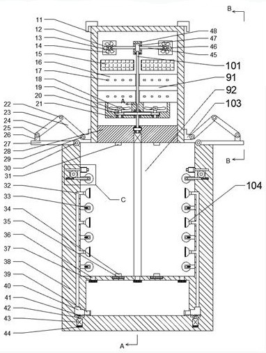
[0017] Combine below Figure 1-5 The present invention is described in detail, wherein for the convenience of narration, the orientations mentioned below are stipulated as follows now: figure 1 The up, down, left, right, front and back directions of the projection relationship itself are the same.

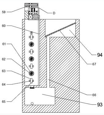
[0018] combined with Figure 1-5The protection and cleaning equipment for a communication cabinet includes a cabinet body 11 and a housing 38 fixedly arranged below the cabinet body 11, a working chamber 91 is arranged inside the cabinet body 11, and a working chamber 91 is arranged inside the housing body 38. There is a sliding chamber 92 with an upward opening, and a water storage chamber 93 is provided at the bottom of the housing 38, and the water storage chamber 93 communicates with an upwardly opening filter chamber 94 through a water injection pipe 66, and the filter chamber 94 is arranged in the shell The top of the rear of body 38, the water injection pipe 66 is fixedly ...


PUM


Abstract

The invention discloses communication cabinet protecting and cleaning equipment which comprises a cabinet body and a shell fixedly arranged below the cabinet body, a working cavity is formed in the cabinet body, a sliding cavity with an upward opening is formed in the upper portion of the interior of the shell, and a water storage cavity is formed in the bottom of the shell; the water storage cavity is communicated with a filtering cavity with an upward opening through a water injection pipe, the filtering cavity is formed in the top of the rear portion of the shell, the water injection pipe is fixedly arranged in the shell, an upper socket and a lower socket are fixedly arranged on the cabinet body in the working cavity, and a plurality of inserting openings are fixedly formed in the sockets. The communication cabinet protecting and cleaning equipment is simple in structure and convenient to operate, the communication cabinet can be protected in an extremely severe environment, all procedures are matched with one another without influence, the communication cabinet can be cleaned while being protected, the waste of manpower and material resources is effectively avoided, and therefore, the cost is greatly reduced.

Description

technical field [0001] The invention relates to the related field of communication cabinets, in particular to protection and cleaning equipment for communication cabinets. Background technique [0002] In the mobile communication system, the communication cabinet is an important part of it. When the entire mobile communication system is running, the communication cabinet needs to transfer the signal in the cabinet to the set top and then to the antenna to transmit the signal. The communication cabinet serves as Communication base stations provide physical working environment and safety system equipment. Base station equipment, power supply equipment, transmission equipment, etc. are installed in the cabinet to provide reliable mechanical space for the normal operation of internal equipment. However, the existing communication cabinets are still in actual use. There are certain disadvantages. For example, heat is easily generated inside, and the temperature is too high, which...

Claims


Application Information

Patent Timeline
IPC IPC(8): H05K7/20B08B3/02B08B3/08B08B13/00
CPCB08B3/02B08B3/08B08B13/00H05K7/20172
Inventor 叶锌
Owner 南京斯特孚贸易有限公司
Why Eureka
Try Eureka