Sensor laser welding device

A laser welding and sensor technology, applied in laser welding equipment, auxiliary devices, welding equipment, etc., can solve problems such as incomplete automation

Pending Publication Date: 2021-03-30
无锡市时盛激光科技有限公司
View PDF0 Cites 2 Cited by
  • Summary
  • Abstract
  • Description
  • Claims
  • Application Information

AI Technical Summary

Problems solved by technology

[0004] Therefore, the technical problem to be solved by the present invention is to overcome the defects of incomplete automation in the prior art, thereby providing a sensor laser welding device

Method used


Image

  • Sensor laser welding device
  • Sensor laser welding device
  • Sensor laser welding device

Examples


Embodiment Construction

[0026] In order to make the object, technical solution and advantages of the present invention clearer, the present invention will be further described in detail below in conjunction with the accompanying drawings and embodiments. It should be understood that the specific embodiments described here are only used to explain the present invention, not to limit the present invention.

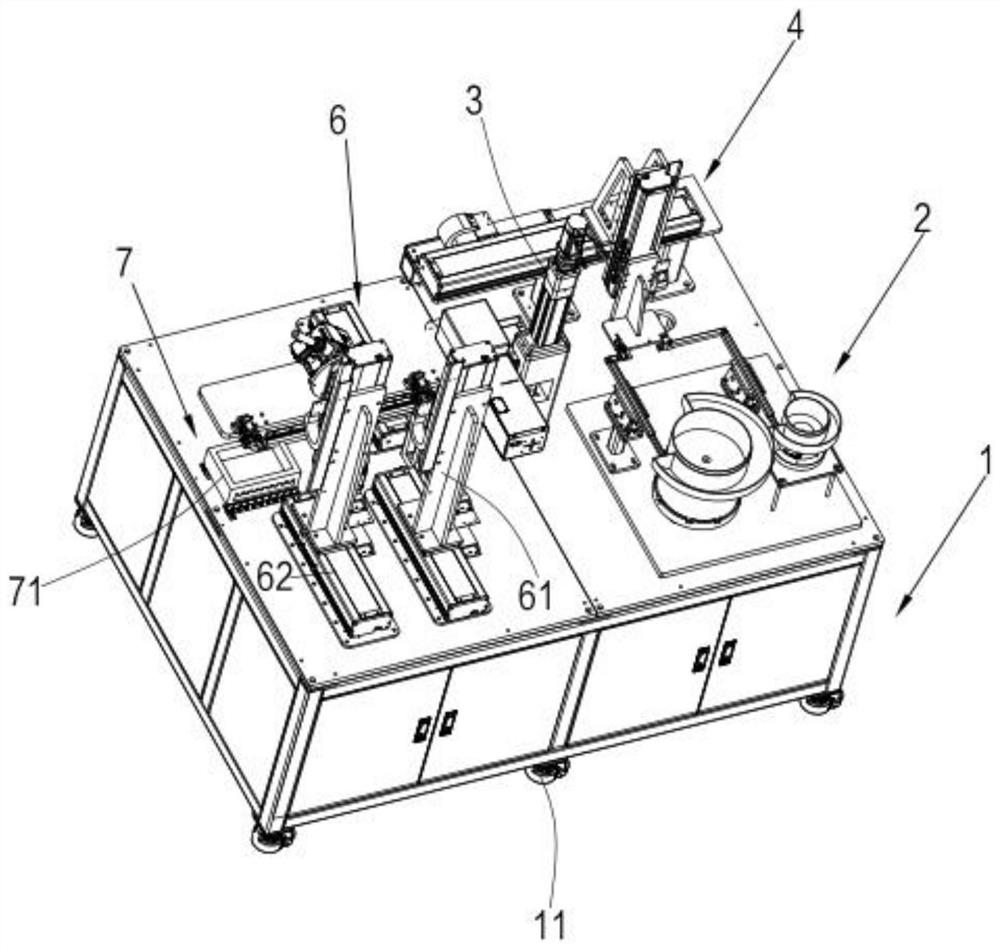
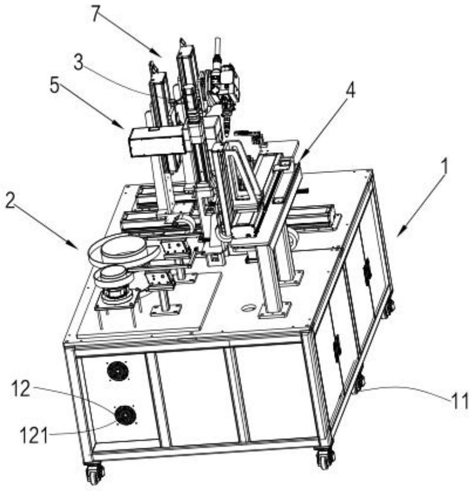
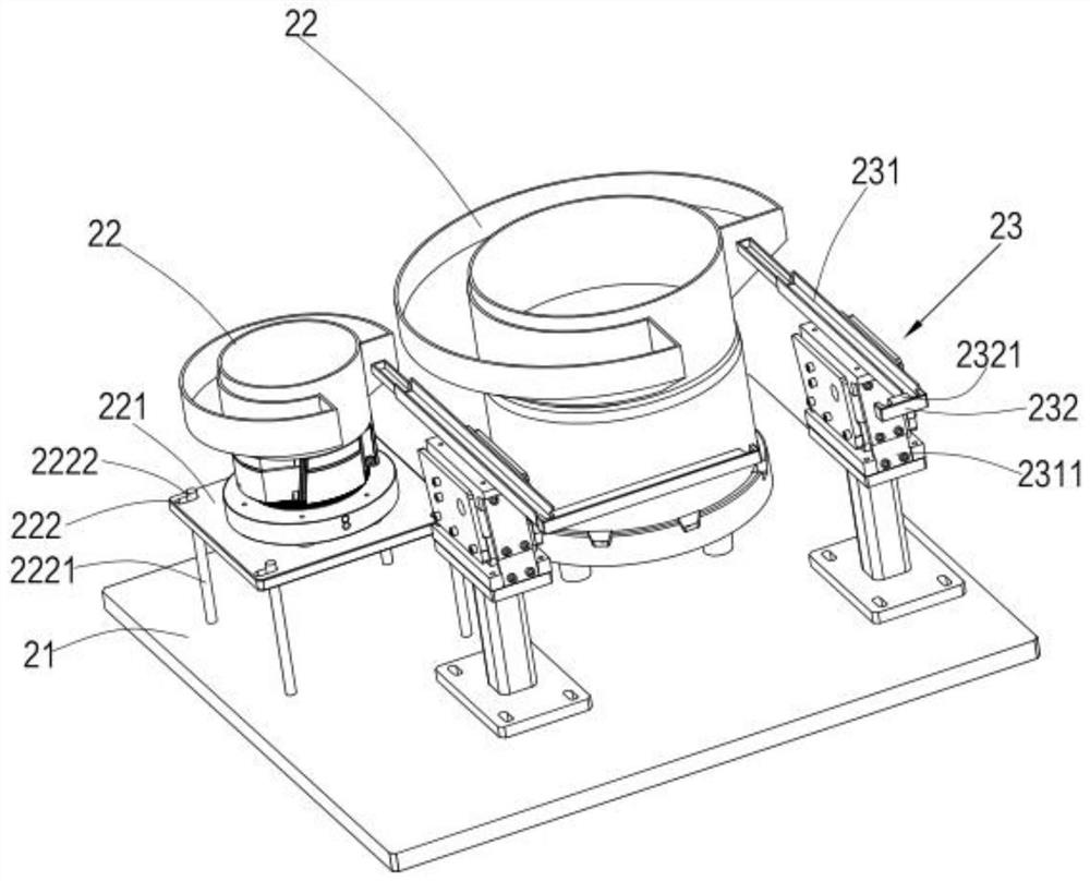
[0027] see figure 1 and figure 2 , a laser welding device for sensors, including a frame 1, a feeding assembly 2, a pre-clamping assembly 3, a moving assembly 4, a positioning assembly 5, a welding assembly 6, a receiving assembly 7 and a control assembly, the frame 1 A laser welding device for supporting the sensor, the feeding assembly 2, the pre-clamping assembly 3, the moving assembly 4, the positioning assembly 5, the welding assembly 6, and the receiving assembly 7 and the control assembly are respectively fixed above the frame 1, the feeding assembly 2 is used for the transmission of the ...


PUM


Abstract

The invention relates to the technical field of sensor welding, in particular to a sensor laser welding device, and aims to solve the problems of incomplete automation and inconvenient welding in theprior art. The sensor laser welding device is characterized by comprising a rack, a feeding assembly, a pre-clamping assembly, moving assemblies, a positioning assembly, a welding assembly and a receiving assembly; the rack is used for supporting the sensor laser welding device; one of the two moving assemblies is located between the feeding assembly and the pre-clamping assembly; and the other moving assembly is located on one side of the pre-clamping assembly, the positioning assembly, ,the welding assembly and the material collecting assembly. Through the arrangement of the two moving assemblies, all stations are tightly combined, and automatic production is effectively achieved; and through the arrangement of the pre-clamping assembly, a capillary tube and a blind cover are pre-clampedin a three-point mode before welding, and the blind cover is prevented from moving in the capillary tube in a welding process.

Description

technical field [0001] The invention relates to the technical field of sensor welding, in particular to a sensor laser welding device. Background technique [0002] Laser welding technology is a high-tech. Due to its unique characteristics, it is especially suitable for use in sensor sealing welding. At present, many foreign manufacturers of sensors use laser welding technology to produce sensors, but there are not many domestic manufacturers using this technology. Mainly some manufacturers of military sensor products and some scientific research institutions are using this process, and more foreign laser welding machines are used. [0003] Laser welding in the prior art generally has a low degree of automation and low production efficiency. Contents of the invention [0004] Therefore, the technical problem to be solved by the present invention is to overcome the defect of incomplete automation in the prior art, so as to provide a sensor laser welding device. [0005] A...

Claims


Application Information

Patent Timeline
Patent Type & Authority Applications(China)
IPC IPC(8): B23K26/21B23K26/70B23K37/04B23K26/08
CPCB23K26/0884B23K37/0435B23K26/21B23K26/702
Inventor 周训全沈海军
Owner 无锡市时盛激光科技有限公司
Why Eureka
Try Eureka