
Robot three-degree-of-freedom wrist device

A technology with a degree of freedom and robotics, applied in the field of robotics, can solve problems such as dependence on imports and low product levels, and achieve the effects of simple structure, convenient use, and improved flexibility and operating space

Inactive Publication Date: 2021-03-30
CHANGSHA UNIVERSITY OF SCIENCE AND TECHNOLOGY
View PDF7 Cites 0 Cited by
  • Summary
  • Abstract
  • Description
  • Claims
  • Application Information

AI Technical Summary

Problems solved by technology

[0002] With the continuous application of robot technology, the robot wrist has become one of the research hotspots in the field of robots. In the field of new technology development, industrial robots are a very important technology. Sensing technology has formed the current high-tech robot technology, which is widely integrated into all aspects of our modern society, and plays a pivotal role in many fields such as aerospace, industrial production and medical education; the wrist device is an important part of the manipulator. On the one hand, the robot wrist device makes the manipulator have a more anthropomorphic shape structure, on the other hand, it can enhance the flexibility and operating space of the manipulator. In recent years, the field of robotics in my country has also developed rapidly, and domestic enterprises engaged in the robotics industry are also increasing. There are more, but the current situation that the product level is not high and key components rely on imports, especially in some special robot wrists, there are many gaps. Therefore, a new type of robot wrist device with three degrees of freedom is urgently needed at this stage.

Method used


Image

  • Robot three-degree-of-freedom wrist device
  • Robot three-degree-of-freedom wrist device
  • Robot three-degree-of-freedom wrist device

Examples


Embodiment Construction

[0019] The following will clearly and completely describe the technical solutions in the embodiments of the present invention with reference to the accompanying drawings in the embodiments of the present invention. Obviously, the described embodiments are only some, not all, embodiments of the present invention. Based on the embodiments of the present invention, all other embodiments obtained by persons of ordinary skill in the art without making creative efforts belong to the protection scope of the present invention.

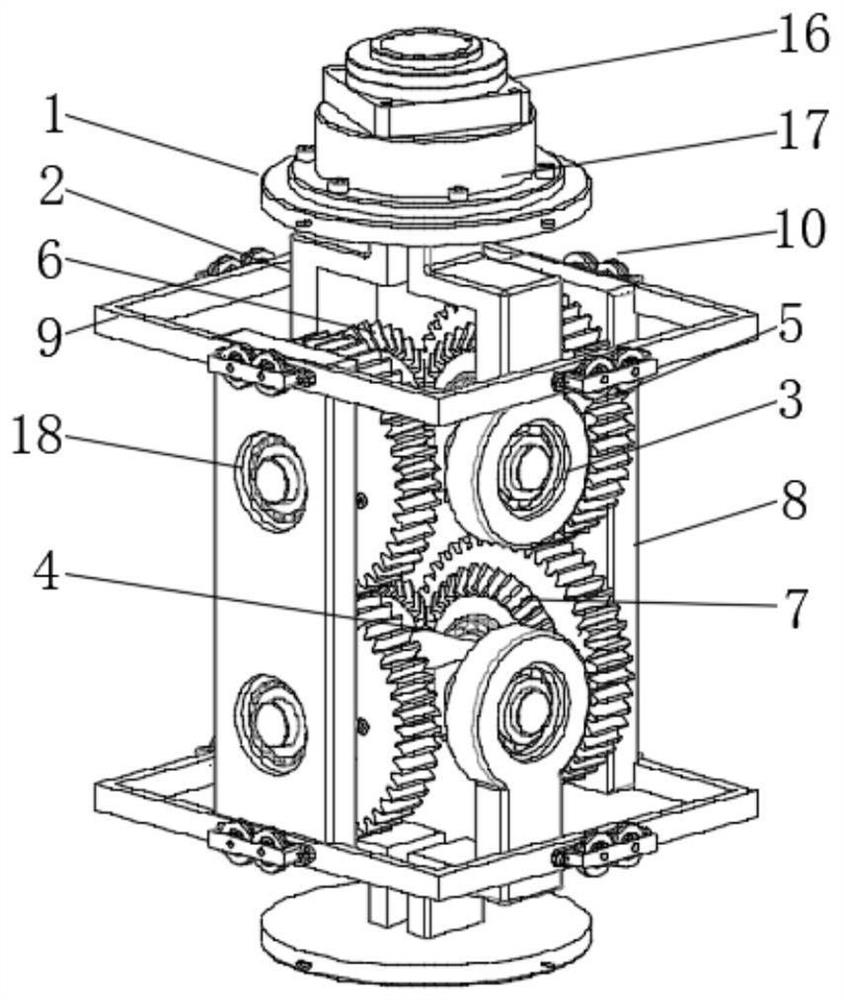
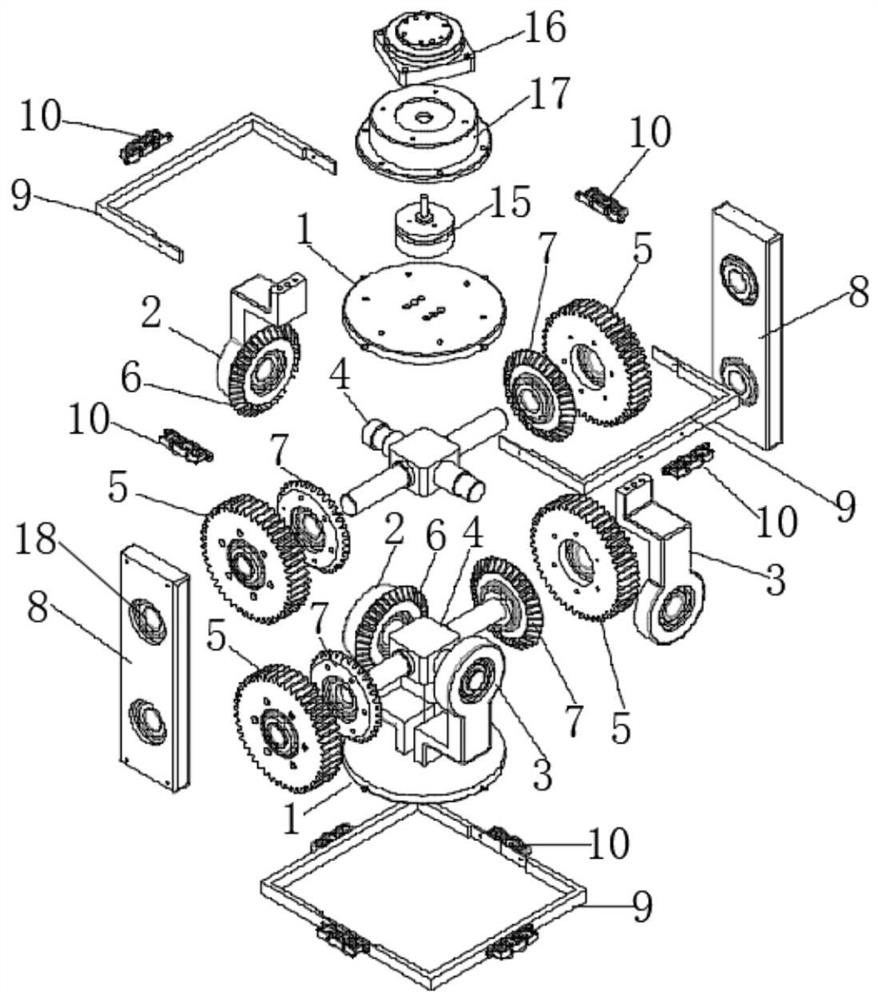
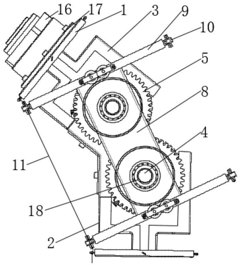
[0020] see Figure 1-6 , the present invention provides a technical solution: a robot wrist device with three degrees of freedom, including a flange 1, a connecting rod 2, a support rod 3, a cross shaft 4, a cylindrical spur gear 5, a driving bevel gear 6, and a passive bevel gear 7 , side plate 8, coaming plate 9, guide wheel set 10, first steel wire rope 11, second steel wire rope 12, third steel wire rope 13, fourth steel wire rope 14, first motor 15, harmo...


PUM


Abstract

The invention discloses a robot three-degree-of-freedom wrist device. The robot three-degree-of-freedom wrist device comprises flange plates, connecting rods, supporting rods, cross shafts, cylindrical straight gears, driving bevel gears, driven bevel gears, side plates, surrounding plates, guide wheel sets, a first steel wire rope, a second steel wire rope, a third steel wire rope, a fourth steelwire rope, a first motor, a harmonic reducer, a motor frame and rotating holes, wherein the guide wheel sets are fixedly connected to the outer walls of the surrounding plates in a distributed mode;and the side plates are symmetrically and fixedly connected to the inner walls of one sides of the surrounding plates. The robot three-degree-of-freedom wrist device is simple in structure and convenient to use; through cooperative use of the cross shafts, the cylindrical straight gears, the driving bevel gears, the driven bevel gears, the guide wheel sets, the steel wire ropes, the first motor and the harmonic speed reducer, the structure is simple; and through user-friendly appearance structural design, pitching, deflection and rotary motion of the wrist device are achieved, the flexibilityand the operation space of the robot wrist device are improved, and use is convenient.

Description

technical field [0001] The invention relates to the technical field of robots, in particular to a three-degree-of-freedom wrist device for a robot. Background technique [0002] With the continuous application of robot technology, the robot wrist has become one of the research hotspots in the field of robots. In the field of new technology development, industrial robots are a very important technology. Sensing technology has formed the current high-tech robot technology, which is widely integrated into all aspects of our modern society, and plays a pivotal role in many fields such as aerospace, industrial production and medical education; the wrist device is an important part of the manipulator. On the one hand, the robot wrist device makes the manipulator have a more anthropomorphic shape structure, on the other hand, it can enhance the flexibility and operating space of the manipulator. In recent years, the field of robotics in my country has also developed rapidly, and dome...

Claims


Application Information

Patent Timeline
IPC IPC(8): B25J17/02
CPCB25J17/0258
Inventor 黄龙杨远汉李晋胡波尹来容
Owner CHANGSHA UNIVERSITY OF SCIENCE AND TECHNOLOGY
Learn More