Timely speed regulation internal gear planetary gear train mechanism of multi-rotor unmanned aerial vehicle

A multi-rotor unmanned aerial vehicle and planetary gear system technology, which is applied to aircraft parts, aircraft power transmission, aircraft power devices, etc., can solve the problems of difficult control of multi-rotor oil-powered unmanned aerial vehicles and difficulty in guaranteeing the rotor speed

Pending Publication Date: 2020-10-30
黑龙江翼飞科技有限公司
View PDF0 Cites 0 Cited by
  • Summary
  • Abstract
  • Description
  • Claims
  • Application Information

AI Technical Summary

Problems solved by technology

[0004] Aiming at the shortcomings of existing multi-rotor oil-powered UAVs, the purpose of the present invention is to provide a multi-rotor UAV with a timely speed-regulating internal gear planetary gear

Method used


Image

  • Timely speed regulation internal gear planetary gear train mechanism of multi-rotor unmanned aerial vehicle
  • Timely speed regulation internal gear planetary gear train mechanism of multi-rotor unmanned aerial vehicle

Examples


specific Embodiment approach 1

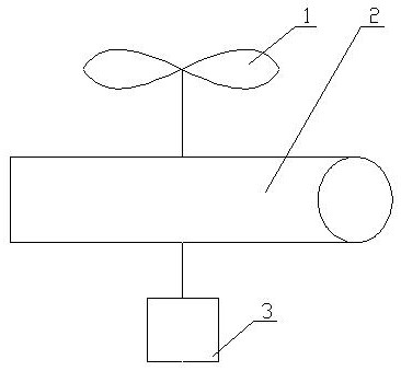
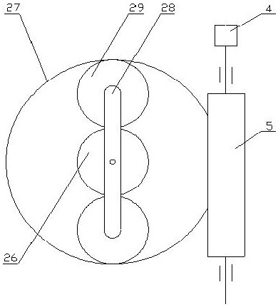
[0019] Specific implementation mode one: as figure 1 , figure 2 As shown, this embodiment discloses a multi-rotor unmanned aerial vehicle timely speed-adjustable internal tooth planetary gear train mechanism, which consists of a rotor 1, a planetary gear train 2, an engine 3, a speed-regulating motor 4, and a worm gear pair 5; The output shaft of the speed-regulating motor 4 is connected to one end of the worm of the worm-gear pair 5, and the worm of the worm-gear pair 5 is meshed with the ring gear 27 of the planetary gear train 2; the output shaft of the engine 3 is connected to the planetary gear The center wheel 26 of the gear train 2 is unidirectionally or fixedly connected; the middle part of the tie rod 28 of the described rotor 1 is unidirectionally or fixedly connected with the planetary gear train 2 .

specific Embodiment approach 2

[0020] Specific implementation mode two: as figure 1 , figure 2 As shown, a kind of multi-rotor unmanned aerial vehicle described in the specific embodiment 1 timely adjusts the internal tooth planetary gear train mechanism, and the described planetary gear train 2 includes the sun gear 26, the ring gear 27, the tie rod 28 and two Planetary gear 29; the central gear 26 and two or more planetary gears 29 are all arranged inside the ring gear 27, the central gear 26 meshes with two or more planetary gears 29 at the same time, and the planetary gear 29 is about the central gear 26 is symmetrical to the center; the planetary gear 29 is internally meshed with the ring gear 27 at the same time, and the two ends of the axles of the central gear 26 and the planetary gear 29 are respectively connected in rotation with the tie rod 28 through bearings.

specific Embodiment approach 3

[0021] Specific implementation mode three: as figure 1 , figure 2 As shown, a kind of multi-rotor unmanned aerial vehicle described in the specific embodiment 1 timely adjusts the internal tooth planetary gear train mechanism, and the worm gear is fixed on the internal ring gear 27, and the two can be split, that is, the internal ring gear and the worm gear are The two parts are fixed together by bolts, rivets, welding, jacking screws, keys, or designing a specific structure. At this time, the gear teeth and worm gear teeth may not be on the same plane; they can also be integrated , that is, the inner side of the ring gear is gear teeth, and the outer side is worm gear teeth. At this time, the gear teeth and worm gear teeth may not be on the same plane.

[0022] Working principle: engine 3 (direct drive engine) transmits power to rotor 1 through planetary gear train 2. The rotational speed of the rotor 1 is equal to the synthesis of the rotational speed of the engine 3 and ...


PUM


Abstract

The invention discloses a timely speed regulation internal gear planetary gear train mechanism of a multi-rotor unmanned aerial vehicle, whichbelongs to the technical field of unmanned aerial vehicles. The timely speed regulation internal gear planetary gear train mechanism of the multi-rotor unmanned aerial vehiclecomprises rotors, a planetary gear train, an engine, a speed regulation motor and aworm, wherein an output shaft of the speed regulation motor is in transmission connection with one end of the worm, and the worm is meshed with an inner gear ring of the planetary gear train; an output shaft of the engine is in one-way or fixed connection with a center wheel of the planetary gear transmission mechanism, and the rotors are in one-way or fixed connection with the middle of a tie bar of the planetary gear train. The problem that the rotating speeds of all engines of an oil-driven multi-rotor unmanned aerial vehicle are difficult to keep consistent is solved.

Description

technical field [0001] The invention relates to a gear train mechanism of a transmission system of an unmanned aerial vehicle, in particular to a gear train mechanism of a multi-rotor unmanned aerial vehicle with timely speed regulation internal tooth planetary gear train, and belongs to the technical field of unmanned aerial vehicles. Background technique [0002] Oil-powered multi-rotor drones are also a common type of plant protection drones on the market because of their good wind resistance, heavy load, and strong endurance. At present, the payload of oil-powered multi-rotor UAVs on the market generally ranges from 30L to 80L, and the operating efficiency of oil-powered multi-rotor UAVs with a load of 60kg is about 3,000 mu / day to 5,000 mu / day. [0003] Oil-driven multi-rotor UAVs can be divided into oil-driven variable pitch and oil-driven direct drive according to the control method. Due to the complex structure, difficult control and maintenance, the oil-driven vari...

Claims


Application Information

Patent Timeline
IPC IPC(8): B64D35/00
CPCB64D35/00
Inventor 不公告发明人
Owner 黑龙江翼飞科技有限公司
Why Eureka
Try Eureka