
Intelligent identification monitoring equipment with anti-collision function

A technology for intelligent identification and monitoring equipment, applied in character and pattern recognition, color TV parts, TV system parts and other directions, can solve problems such as easy impact on support rods, impact on driver's life safety, identification of damage to monitoring cameras, etc. , to achieve the effect of reducing the probability of damage, protecting life and property safety

Inactive Publication Date: 2021-03-30
德清县新市镇恒讯通信器材商行
View PDF9 Cites 0 Cited by
  • Summary
  • Abstract
  • Description
  • Claims
  • Application Information

AI Technical Summary

Problems solved by technology

[0003] As an important part of the license plate information collection, the identification monitoring camera is directly related to the precise operation of the entire system. The current time monitoring camera is generally installed on the side of the access control entrance with a support rod, and does not have the corresponding anti-collision function. For some novice drivers in the When entering and exiting the access control, it is easy to hit the support rod supporting the identification monitoring camera due to improper operation, which will cause damage to the identification monitoring camera, and even affect the life safety of the driver in severe cases

Method used


Image

  • Intelligent identification monitoring equipment with anti-collision function
  • Intelligent identification monitoring equipment with anti-collision function
  • Intelligent identification monitoring equipment with anti-collision function

Examples


Embodiment Construction

[0025] The following will clearly and completely describe the technical solutions in the embodiments of the present invention with reference to the accompanying drawings in the embodiments of the present invention. Obviously, the described embodiments are only some, not all, embodiments of the present invention.

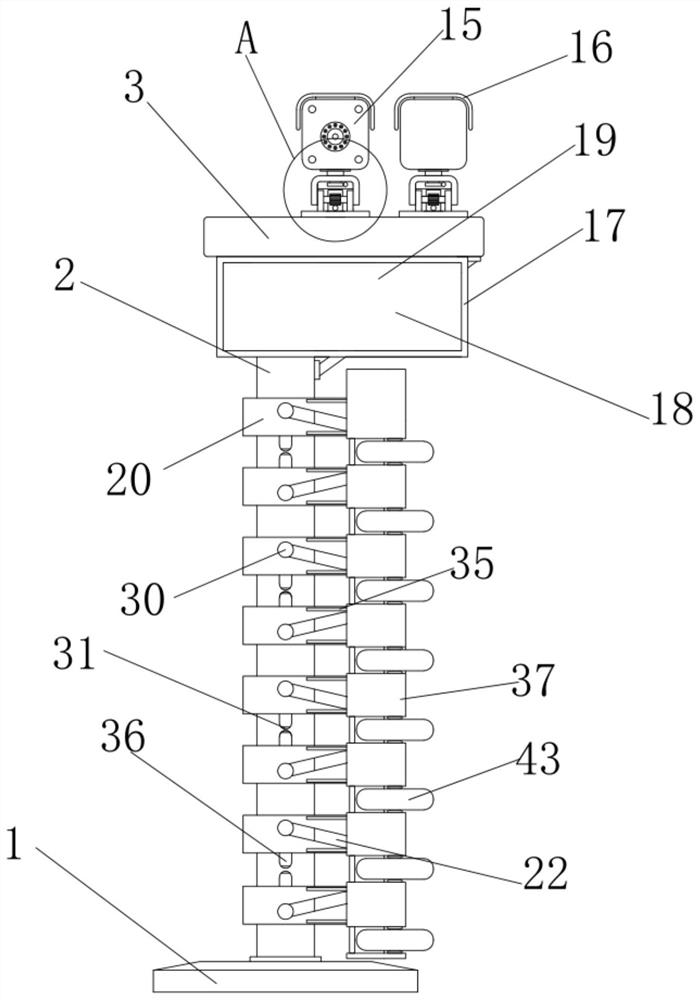
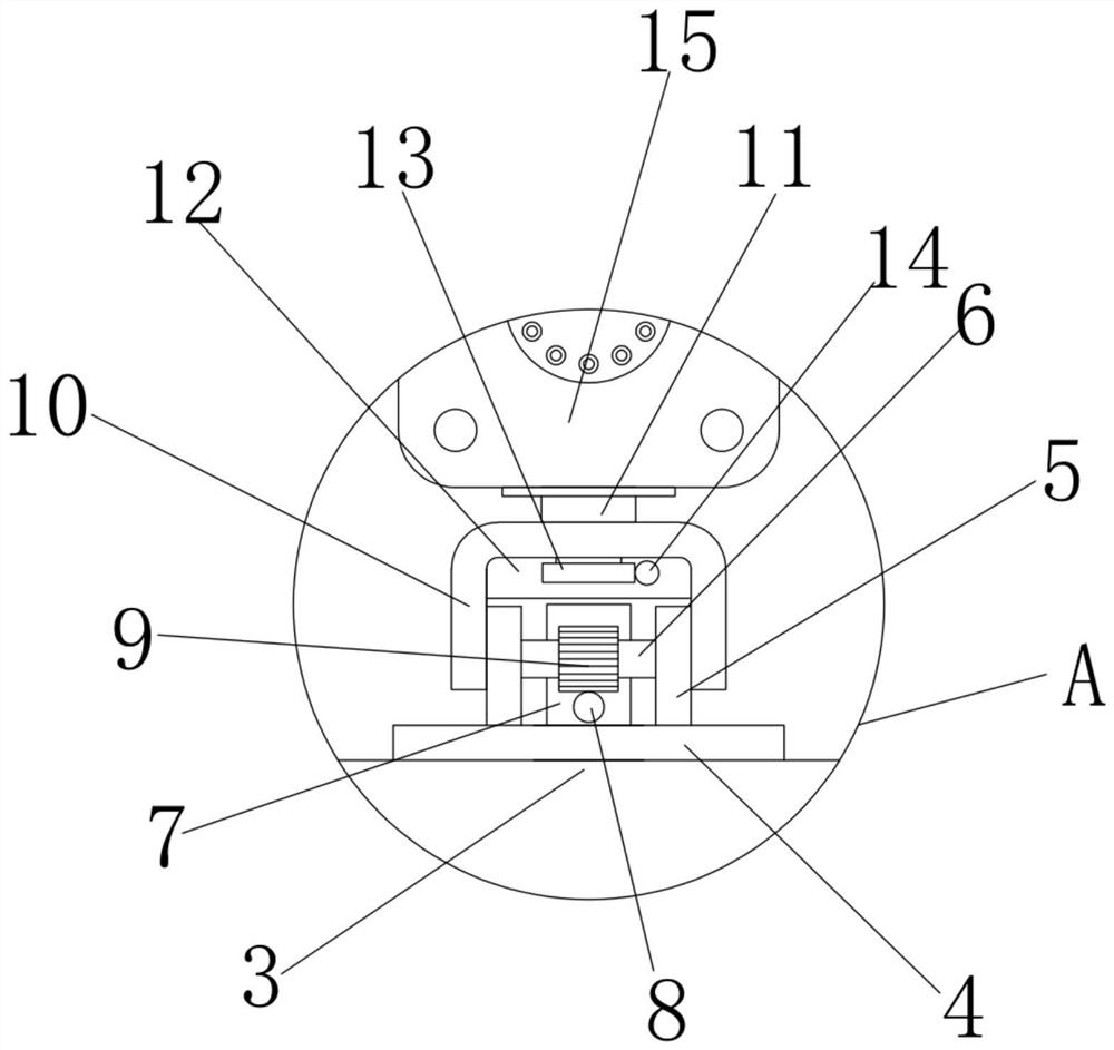
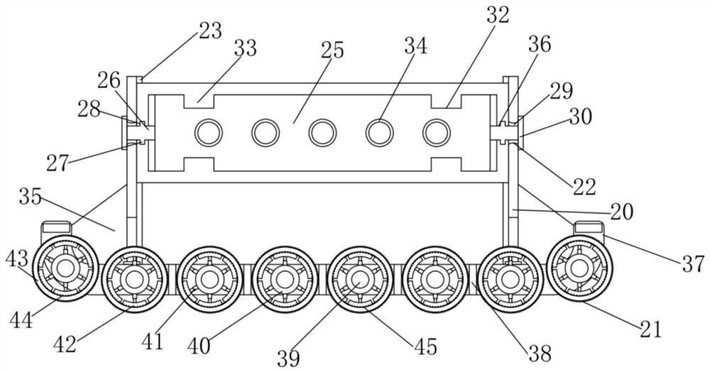
[0026] refer to Figure 1-7, an intelligent identification and monitoring device with anti-collision function, comprising a base 1, a rectangular support tube 2 is fixedly installed at the center of the upper side wall of the base 1, and a mounting plate 3 is fixedly installed on the top of the rectangular support tube 2 away from the base 1, and the installation The upper side wall of the plate 3 is symmetrically fixed with a bottom plate 4, and the upper side wall of the bottom plate 4 is symmetrically fixed with a support plate 5, and a rotating shaft 6 is installed between the two sets of support plates 5, and a U-shaped connection is arranged above the support pl...


PUM


Abstract

The invention relates to the technical field of monitoring equipment and particularly relates to intelligent identification monitoring equipment with an anti-collision function. The equipment comprises a base, wherein a rectangular supporting pipe is fixedly mounted at the center of the upper side wall of the base, and a mounting plate is fixedly mounted at the top end, far away from the base, ofthe rectangular supporting pipe; bottom plates are symmetrically and fixedly mounted on the upper side walls of the mounting plates, supporting plates are symmetrically and fixedly mounted on the upper side walls of the bottom plates, a rotating shaft is rotatably mounted between the two sets of supporting plates, U-shaped connecting pieces are arranged above the supporting plates, and the U-shaped connecting pieces are fixedly connected with the two ends of the rotating shaft; a rotating shaft is rotatably mounted in the center of the upper side wall of the U-shaped connecting piece, a monitoring recognition camera is fixedly mounted at the top end of the rotating shaft, and mounting frames are symmetrically arranged on the two sides of the rectangular supporting pipe. Not only are the monitoring identification camera and the LED display screen protected, but also the probability of damage caused by collision with the automobile is reduced, and the life and property safety of a driveris protected.

Description

technical field [0001] The invention relates to the technical field of monitoring equipment, in particular to an intelligent identification monitoring equipment with anti-collision function. Background technique [0002] With the development of science and technology, more and more community entrances and parking lot entrances have installed license plate recognition systems. The license plate recognition system is an application of computer video image recognition technology in vehicle license plate recognition. License plate recognition is widely used in highway vehicle management, and in electronic toll collection (ETC) system, it is also the main means of identifying vehicle identity combined with DSRC technology. The license plate recognition technology requires the ability to extract and recognize the moving license plate from the complex background, and recognize the vehicle license plate number, color and other information through license plate extraction, image prep...

Claims


Application Information

Patent Timeline
IPC IPC(8): E01F15/14G06K9/20H04N5/225H04N7/18
CPCE01F15/145H04N7/183G06V10/10H04N23/50
Inventor 姚朝星
Owner 德清县新市镇恒讯通信器材商行
Learn More