Vertical vibration attenuation device and method for determining mass of damping liquid medium in vertical vibration attenuation
A determination method and shock absorber technology, applied in the direction of shock absorber, inertial effect shock absorber, shock absorber-spring combination, etc., can solve the problems of unstable performance of shock absorber, large plastic deformation, slow equipment, etc. Achieve the effect of good automatic activation performance, increase damping energy dissipation capacity, and increase energy consumption
- Summary
- Abstract
- Description
- Claims
- Application Information
AI Technical Summary
Problems solved by technology
Method used
Image

Examples
Embodiment 1
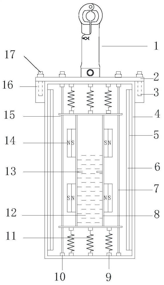
[0055] This embodiment provides an example of a vertical shock absorber as a vertical shock absorber. The shock absorber includes a rectangular inner shell, a rectangular outer shell, a cover plate 2 connected to the rectangular shell, and a The wire chuck 1, the inner shell is a closed inner shell containing a damping liquid medium; the upper and lower ends of the inner shell and the inner wall of the outer shell are respectively provided with damping parts in the axial direction. In this embodiment, the rectangular inner shell is the shell 8 of the damping liquid energy-dissipating vibration-absorbing device, the rectangular shell is the shock absorber shell 4 , and the damping liquid medium is the damping liquid 12 .
[0056] The inner and outer walls of the inner shell have symmetrically arranged shock absorbers.
[0057] The inner wall of the shell is provided with a plate type shock absorber.
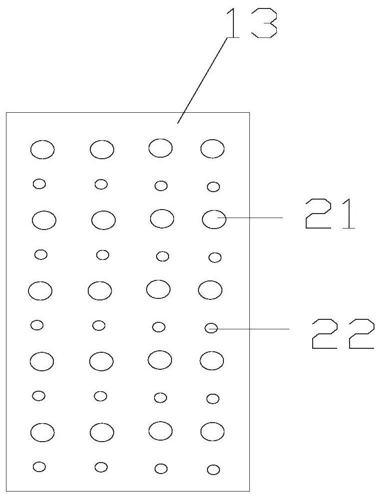
[0058] The shock absorber in the inner shell is a partition 13 perpendicular...
PUM
 Abstract
Description
Claims
Application Information
 - Generate Ideas
- Intellectual Property
- Life Sciences
- Materials
- Tech Scout
- Unparalleled Data Quality
- Higher Quality Content
- 60% Fewer Hallucinations
Browse by: Latest US Patents, China's latest patents, Technical Efficacy Thesaurus, Application Domain, Technology Topic, Popular Technical Reports.
© 2025 PatSnap. All rights reserved.Legal|Privacy policy|Modern Slavery Act Transparency Statement|Sitemap|About US| Contact US: help@patsnap.com