
Resistance testing device for IIR digital filter production and testing method of resistance testing device

A technology of digital filter and test device, applied in the direction of measuring device, measuring device casing, instrument, etc., can solve the problems of poor contact, troublesome operation, affecting the accuracy of test data, etc., and achieve the effect of avoiding blockage and convenient and simple operation.

Active Publication Date: 2021-03-30
ANHUI TECHN COLLEGE OF MECHANICAL & ELECTRICAL ENG
View PDF11 Cites 0 Cited by
  • Summary
  • Abstract
  • Description
  • Claims
  • Application Information

AI Technical Summary

Problems solved by technology

[0006] The purpose of the present invention is to provide a kind of IIR digital filter production resistance testing device and testing method thereof, to solve the problem of the red probe and the black probe of the existing resistance testing device on the market proposed by the above-mentioned background technology. The two ends of the terminal and the resistance are only detected by hand-held contact, which is easy to cause poor contact, which will affect the accuracy of the later test data. The existing resistance test device needs to use a filter mechanism to dissipate heat from the vent. After the filter mechanism has been used for a period of time, the impurities on its surface need to be cleaned, and the operation is more troublesome.

Method used


Image

  • Resistance testing device for IIR digital filter production and testing method of resistance testing device
  • Resistance testing device for IIR digital filter production and testing method of resistance testing device
  • Resistance testing device for IIR digital filter production and testing method of resistance testing device

Examples


Embodiment Construction

[0033] The following will clearly and completely describe the technical solutions in the embodiments of the present invention with reference to the accompanying drawings in the embodiments of the present invention. Obviously, the described embodiments are only some, not all, embodiments of the present invention. Based on the embodiments of the present invention, all other embodiments obtained by persons of ordinary skill in the art without making creative efforts belong to the protection scope of the present invention.

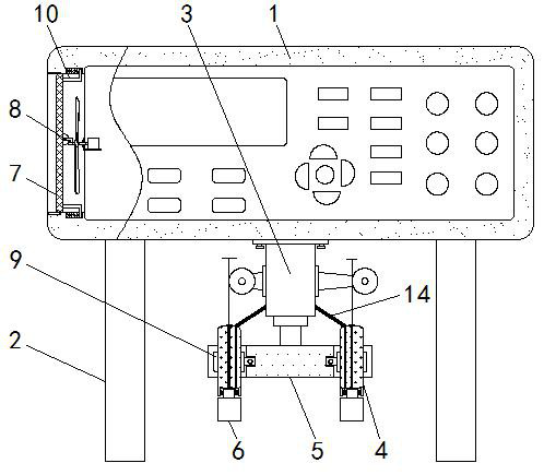
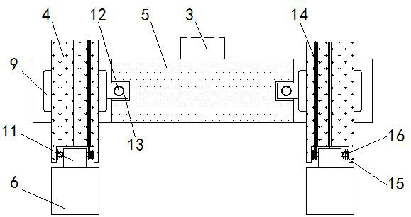
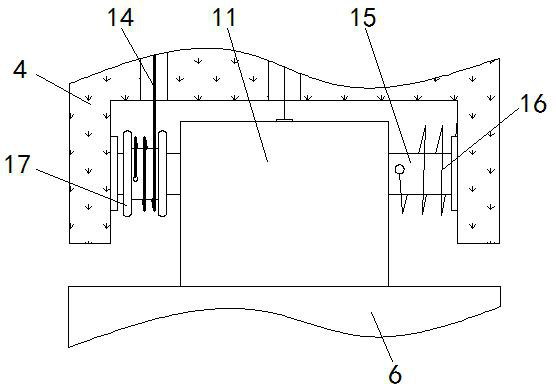
[0034] see Figure 1-7, the present invention provides a technical solution: a resistance test device for IIR digital filter production, including a housing body 1, a support leg 2, an electric push rod 3, a detection probe 4, a fixing plate 5, a detection block 6, a filter Plate 7, cross bar 8, extrusion plate 9, connecting rod 10, connecting block 11, two-way screw rod 12, moving block 13, connecting rope 14, adjusting shaft 15, torsion spring 16, rope windi...


PUM


Abstract

The invention discloses a resistance testing device for IIR digital filter production and a testing method of the resistance testing device. The resistance testing device comprises a shell main body,supporting legs, an electric push rod and a detection probe; the supporting legs are installed at the bottoms of the left end and the right end of the shell main body through screws; and the electricpush rod is installed in the middle of the bottom face of the shell body through a screw; the output end of the electric push rod is connected with a fixing plate through a screw; a filter plate is connected into the left end of the shell body in a clamped mode; a transverse rod is arranged on the right side of the filter plate; the right end of the transverse rod is connected with a bearing of the shell main body; positioning grooves and moving grooves are formed in the inner walls of the upper side face and the lower side face of the left side face of the shell main body; the moving groovesare formed to the right sides of the positioning grooves. According to the resistance testing device for IIR digital filter production and the testing method of the resistance testing device, two detection blocks are installed so that later detection work can be facilitated, a worker does not need to always hold the detection probe to make contact with a resistor, and operation is convenient and easy.

Description

technical field [0001] The invention relates to the related technical field of IIR digital filters, in particular to a resistance test device and a test method for the production of IIR digital filters. Background technique [0002] IIR digital filter is one of various filters. According to different functions and principles, the types of filters are different. IIR digital filter has a feedback loop in the process of filtering. Through IIR digital filter It can reduce the ripple coefficient of the output voltage, thereby making the waveform smoother and reducing signal interference. The resistance value of the IIR digital filter needs to be tested during the production and preparation process, so there are resistance value test device, but there are still certain problems in the use of the resistance test device, such as [0003] 1. When the existing resistance test device is testing the resistance value of the IIR digital filter, it is necessary to contact the bottom ends ...

Claims


Application Information

Patent Timeline
IPC IPC(8): G01R27/02G01R31/00G01R1/04
CPCG01R27/02G01R31/00G01R1/04
Inventor 马运强甘泉席宇迪程涛林海洋
Owner ANHUI TECHN COLLEGE OF MECHANICAL & ELECTRICAL ENG
Learn More